background image

Page 3 

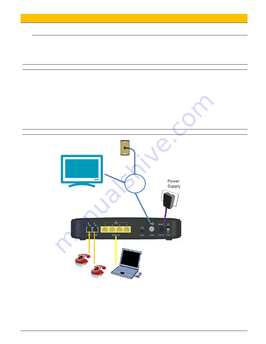
3. Connecting the F@ST3284 Gateway to Your Computer 

Installation Procedure for Ethernet Interface 

Follow the steps below for proper installation: 

1. 

Make sure your computer meets the system requirements. 

2. 

Connect a coaxial cable to the wall plug 

3. 

Connect a coaxial cable to the CABLE connector on the F@ST3284u and screw it at the bottom manually (do not force). 

Note: 

To speed up the registration process of 

F@ST3284u

, the coaxial cable should be connected to the gateway prior to the power connector. 

4. 

Connect the RJ45 Ethernet cable to the 

ETHERNET

 connector on the gateway, connect the other end with the 

10/100/1000BaseT Ethernet port on your computer. 

5. 

Plug the RJ11 telephone cord(s) to the TEL 1 or TEL2 connector (s) of the cable modem. (Plug the RJ11 telephone cord(s) to 
the PSTN connector on the modem, connect to the PSTN service provider. This step is for EMTA with PSTN model only.) 

6. 

Plug the power supply unit into the 

POWER

 connector of the modem. 

7. 

Plug the other end of the power supply unit into a power outlet. 

8. Power ON the F@ST3284u by pressing the ON/O FF button on the rear panel of the F@ST3284u.  

9. 

The cable gateway will look for the proper cable modem signal in the Cable Television network and process the initial 
registration. The cable gateway is ready for data transfer after the LED “

INTERNET

” is in solid white. The gateway is ready to 

make a phone call after the LED “

Tel1

” or “

Tel2

” is in solid white. 

Note:

 The 

RESET

 button at the rear panel is for maintenance purpose only.   


The screen of the coaxial cable is intended to be connected to earth in the building installation 


Cable 

splitter 

Содержание F@ST 3284u

Страница 1: ...compatible with IEEE 802 11a b g n The Wireless access point is operating on 2 4GHz band Package Contents F S T3284u Gateway x1 Ethernet Cable RJ45 x1 Phone Cable RJ11 x1 Quick Start Guide x1 Power Supply Unit x1 2 Hardware Connection 11 10 12 13 14 15 1 2 3 4 5 6 7 8 9 16 LED Power ON OFF 1 2 3 4 5 6 7 8 9 16 10 11 12 13 15 14 LED Downstream indicate receiving RF DS traffic LED Upstream indicate ...

Страница 2: ...unt the Cable Gateway Note When wall mounting the unit ensure that it is within reach of the power outlet To wall mount the unit 1 Ensure that the wall you use is smooth flat dry and sturdy and use the 2 screw holes which are 120 mm apart from each other 2 Fix the screws into wall leaving their heads 3 mm 0 12 inch clear of the wall surface 3 Remove any connections to the unit and locate it over t...

Страница 3: ...1 or TEL2 connector s of the cable modem Plug the RJ11 telephone cord s to the PSTN connector on the modem connect to the PSTN service provider This step is for EMTA with PSTN model only 6 Plug the power supply unit into the POWER connector of the modem 7 Plug the other end of the power supply unit into a power outlet 8 Power ON the F ST3284u by pressing the ON O FF button on the rear panel of the...

Страница 4: ...trol To safely restrict and control the Internet usage to your family Wireless To configure the WiFi network of your F ST3284u MTA To check the telephony status of your F ST3284u Connect by typing Username admin Password admin Click on OK button Under the gateway on the label note the reference of SSID and WPA wireless password Click on Start then on o Network Connection o Wireless network connect...

Страница 5: ... be used with the Power Supply Unit PSU delivered within the same package z The PSU must be plugged to an electrical network delivering a 110V nominal voltage in 60Hz z Protection against short circuits and leakage between phases neutral and earth must be assured by the building s electrical installation The power circuit of this equipment must be fitted with a 16A protection against overcurrent a...

Страница 6: ...o connect to the electrical network the product must be installed near an easily accessed power outlet 6 This equipment should only be operated from the type of power supply Voltage and Current indicated on the marking label 7 Do not overload wall outlets or extension cords Doing so can result in the risk of fire or electrical shock 8 Avoid blocking any vent openings or exhaust exits on this equip...

Страница 7: ...ment Note This equipment has been tested and found to comply with the limits for a Class B digital device pursuant to Part 15 of the FCC Rules These limits are designed to provide reasonable protection against harmful interference in a residential installation This equipment generates uses and can radiate radio frequency energy and if not installed and used in accordance with the instructions may ...

Страница 8: ...n uncontrolled environment This transmitter must not be co located or operating in conjunction with any other antenna or transmitter This device produces radio frequency energy in the 2 4GHz spectrum The antenna must be positioned to keep a minimum distance of 20cm 0 65ft from the radiating element to any nearby person Issued by Sagemcom Broadband SAS Sagemcom 250 route de l Empereur 92500 RUEIL M...

Страница 9: ...need 2 suitable screws which screw diameter would be 5 7 5 mm to wall mount the F ST3284u Note When wall mounting the unit ensure that it is within reach of the power outlet To wall mount the unit 1 Ensure that the wall you use is smooth flat dry and sturdy and use the 2 screw holes which are 120mm 4 72 inch apart from each other 2 Fix the screws into wall leaving their heads 3 mm 0 12 inch clear ...

Страница 10: ...ause harmful interference to radio communications However there is no guarantee that interference will not occur in a particular installation If this equipment does cause harmful interference to radio or television reception which can be determined by turning the equipment off and on the user is encouraged to try to correct the interference by one of the following measures Reorient or relocate the...

Страница 11: ...trolled environment This equipment should be installed and operated with minimum distance 20cm between the radiator your body Note The country code selection is for non US model only and is not available to all US model Per FCC regulation all WiFi product marketed in US must fixed to US operation channels only ...

Отзывы: