


48
Be sure the tool frame is securely supported and cannot be tipped over during this
installation procedure. An additional person should support and stabilize the frame at all
times during the installation.
1.
Position the stop bar in the bottom left side of the frame as shown in Fig. 52, resting against the bottom
horizontal arm and the vertical back supports.
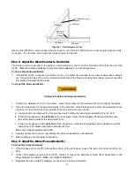
Figure 52: Installing the Stop Bar
2.
Working from the front of the tool, attach the three angle supports (Fig. 53) to the back of the Stop Bar, using
six 5/16 x 3/4” (7.9mm x 19.05mm) hex-head cap screws and nuts. Tighten the nuts securely.
Figure 53: Installing the Stop Bar
(viewed from the rear)
3. Push the stop bar housing as far toward the center of the tool as possible.
3.
Working from the back of the machine, use the angle supports as templates to drill six 7/32” (5.55mm) holes
(two per bracket) in the horizontal tubes of the frame.
4.
Insert and tighten six self-tapping
¼
- 20 (6.35mm) hex-head screws to secure the angle support brackets to the
frame tubes.
5.
Measure out from the blade and adjust the stop bar ruler by sliding it left or right inside its aluminum extension.
Operation
Set the individual flip stops to the positions desired for repetitive cuts: loosen the collars with the provided Allen
wrench, slide the collars to the desired position, and retighten them.
Multiple cuts can be made by flipping the stops up or down to position the work piece at the proper distance from
the blade or bit. When setting multiple stops, remember to account for the material lost to the blade kerf.
Stop Bar
Use as template to
drill 7/32” (5.55mm)
holes.
Angle Support
Stop Bar


