background image

700-9700 


7.14.2022 

10 

 
It is not necessary to fully discharge the battery prior to charging. Battery should be charged daily and cannot be 
overcharged. It takes up to twelve hours to fully charge depending upon battery usage 
 
Do not drop the battery, as it could cause the unit to fail. If the battery case is cracked do not use and replace the 
battery. During temperature extremes beyond the range of 41

˚F (5˚C) to 104˚F (40˚C) remove battery and place 

in a controlled environment or battery life may be shortened. 


Battery Disposal

 - The batteries located inside the battery pack are recyclable and shall be disposed of in 

accordance with applicable local, state/provincial, or federal/national regulations. 

 
Locking Plate Assembly

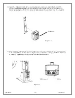
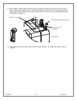
 - The battery pack can be secured to the mounting plate using the provided lock plate 

assembly. To install open the lock plate so that the bottom tabs are moved close to one another to allow the lock 
plate to be inserted into the slots on the mounting plate secured to the lift. Close the lock plate assembly so that 
the tabs are captured by the slots. Insert a padlock (not provided) through the holes on the lock plate assembly 
to secure it.  


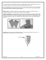
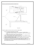
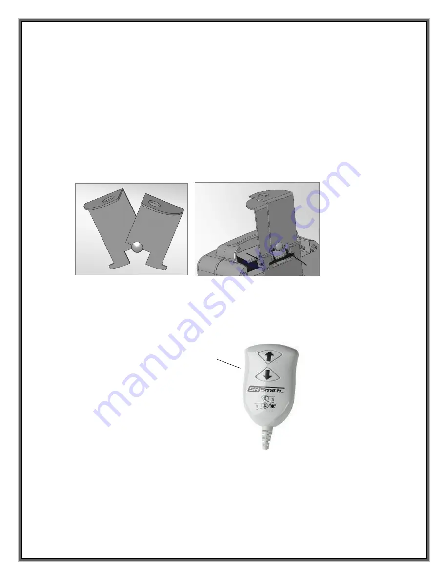
Hand Control 

 The two button unit controls lift movement. The arrows indicate direction of movement. The 

Hand Control is fully waterproof and meets IP67 standards.   


1001601 

Содержание multiLift 2

Страница 1: ... 2022 1 multiLiftTM 2 POOL LIFT S R SMITH LLC CORPORATE HEADQUARTERS P O Box 400 1017 S W Berg Parkway Canby Oregon 97013 USA Phone 503 266 2231 Fax 503 266 4334 www srsmith com OWNER S MANUAL MAINTENANCE PROCEDURES ...

Страница 2: ...WATER 30 STANDARD ACCESSORIES OPTIONAL ACCESSORIES 31 MAINTENANCE and CLEANING 31 TROUBLE SHOOTING 32 LONG TERM STORAGE 32 WARRANTY INFORMATION 33 SPECIFICATIONS 34 1 Dimensions Capacity 34 2 Actuator 34 3 Battery 34 4 Range of MotionInformation 34 5 Noise 34 6 Materials and Finish Information 34 APPENDIX A multiLift2 SEAT w FOOTREST 160 9200 35 APPENDIX B NEW CONSTRUCTION JIG 500 5000A 36 APPENDI...

Страница 3: ...of charge Before installing the pool lift the installer must review and confirm the information provided on the Deck Profile Sheet If the description of the application does not match the installation site a new Deck Profile Sheet must be completed and submitted to S R Smith NOTE FAILURE TO COMPLETE AN ACCURATE DECK PROFILE SHEET MAY RESULT IN THE LIFT NOT MEETING ADA COMPLIANCE GUIDELINES To comp...

Страница 4: ... forth by the Access Board ADAAG 2004 The lift system and AC powered battery charger complies with EN60601 1 2 2007 03 Using the multiLift2 Obey all User Instructions listed in the Owner s Manual whenever using lift Obey all Caution Warning Operating Instruction s and Labels located on the lift whenever using It is the responsibility of the lift Owner to ensure that the correct safety procedures h...

Страница 5: ...ver the deck a minimum of 16 from the edge of the pool 1009 2 3 Clear Deck Space On the side of the seat opposite the water a clear deck space shall be provided parallel with the seat The space shall be 36 wide minimum and shall extend forward 48 minimum from a line located 12 behind the rear edge of the seat 1009 2 4 Seat Height The lift shall stop at 16 19 measured from the deck to the top of th...

Страница 6: ...ssary to achieve safe reliable and proper performance of the lift and avoid injury This ensures consistent safe operation and minimizes service problems The multiLift2 has a mast height of 58 5 in 148 6 cm above the deck It is intended to be used with simple pool gutter configurations having a deck to water distance of no more than 14 5 see Figure 19 on page 24 to determine if the multiLift2 is ap...

Страница 7: ...controls all lift operations identical to the user handset Two cables connect to the bottom of the Control Box to enable operation of the lift The largest connector is for the hand control Connector 2 is for the actuator cable Touchpad Control The touchpad control arrow keys can be used in the event the Hand Control is out of reach or fails Simply press and hold the arrow for the desired action fo...

Страница 8: ...el LED will flash If the unit has a problem downloading the performance log the Red less than 25 LED will flash Remove the USB from the port and re insert it If the Red 25 LED flashes again confirm that the USB you are using is FAT file formatted The information from the USB can be downloaded to a PC for review and or copied to a spread sheet The performance log will retain approximately 7 600 eve...

Страница 9: ...ge as it will shorten battery life The battery pack has an LED indicator near the plug in port It will glow Red when first plugged into the transformer If the LED remains Red this indicates the battery pack needs charging When fully charged the LED will glow Green If the battery is fully charged and is plugged into the transformer the LED will glow Red for approximately 10 sec then glow Green If t...

Страница 10: ...ery pack are recyclable and shall be disposed of in accordance with applicable local state provincial or federal national regulations Locking Plate Assembly The battery pack can be secured to the mounting plate using the provided lock plate assembly To install open the lock plate so that the bottom tabs are moved close to one another to allow the lock plate to be inserted into the slots on the mou...

Страница 11: ...ment The multiLift2 can be installed using existing multiLift and ML300 anchors The multiLift2 is shipped partially assembled Position container s close to deck anchors for easier assembly and set up Unpacking Assembly Procedure for the multiLift2 1 Carefully remove all lift components from packaging 2 Remove seat assembly and footrest and set aside for attachment 3 Align slotted holes in the base...

Страница 12: ...he multiLift2 comes standard with the ability to mount the seat on either side of the lift Follow assembly instructions starting on page 13 for mounting the seat on the RIGHT side of the lift and page 17 for mounting the seat on the LEFT side of the lift LEFT HAND CONFIGURATION RIGHT HAND CONFIGURATION ...

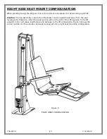
Страница 13: ...sure the lift actuator motor is positioned away from the seat leveling arm Failure to install the seat leveling arm on the side of the lift opposite to the lift actuator motor will cause interference and damage to the lift components Figure 5 shows the correct position for the actuator and seat leveling arm for a right seat mounting configuration Figure 5 RIGHT HAND CONFIGURATION ...

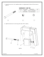
Страница 14: ...700 9700 7 14 2022 14 7 Install the seat arm to the multiLift2 assembly by using Hardware Kit 580 7100 as shown in Figure 6 8 Tighten bolt and lock nut until snug then back off 1 2 rotation Figure 6 ...

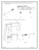
Страница 15: ...700 9700 7 14 2022 15 9 Use Hardware Kit 580 7200 to attach the seat leveling arm to the seat arm as shown in Figure 7 10 Tighten bolt and lock nut until snug then back off 1 2 rotation Figure 7 ...

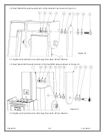
Страница 16: ...t leveling arm to the multiLift2 base as shown in Figure 8 12 Tighten bolt and lock nut until snug then back off 1 2 rotation Note This completes the right mount configuration please skip to page 21 for the balance of assembly instructions Figure 8 ...

Страница 17: ... of the lift opposite to the lift actuator motor will cause interference and damage to the lift components Figure 9 shows the correct position for the actuator and seat leveling arm for a left seat mounting configuration The main assembly for the multiLift2 is shipped with the actuator installed in the right seat mount configuration When assembling the lift for a left seat mount configuration the ...

Страница 18: ...t it is in the position shown in Figure 9 and reattach the actuator Figure 10 shows the re assembly sequence for bolt washer spacers and nut CAUTION This configuration modification can be challenging so it s best 2 two people assist each other to get the spacers back in place and the lift does NOT deploy move Figure 10 ...

Страница 19: ... 9700 7 14 2022 19 14 Install the lift seat arm to the multiLift2 assembly by using Hardware Kit 580 7100 as shown in Figure 11 15 Tighten bolt and lock nut until snug then back off 1 2 rotation Figure 11 ...

Страница 20: ...e seat arm as shown in Figure 12 17 Tighten bolt and lock nut until snug then back off 1 2 rotation 18 Next assemble the seat leveling to the multiLift2 base as shown in Figure 13 19 Tighten bolt and lock nut until snug then back off 1 2 rotation Figure 12 Figure 13 ...

Страница 21: ...nd attach to Seat Frame using bolt 2 Washers and 1 Acorn Nut Tighten using 2 Box Wrenches See Figure 14 21 Attach the Footrest to the Seat using 2 bolts and 2 4 arm knobs through holes on bottom of Seat and Footrest See Figure 15 Figure 14 Figure 15 ...

Страница 22: ...ller to the bracket by installing the 10 32 X 3 8 screw and tightening with the wrench provided See Figure 16 23 Remove the Hand Control from accessory carton and unwrap Insert Hand Control plug into large socket on the LiftOperator Control Box shown in Figure 17 Next install the actuator plug into the socket shown in Figure 17 Route actuator cable from the motor as shown in Figure 17 1001494 Figu...

Страница 23: ...he battery from the control unit 1 pull outward on the battery handle until the battery latch bracket clears the slots in the control unit mounting bracket 2 then pull upward see Figure 18 25 Check all controls and emergency stop button for proper operation See LiftOperator Owner s Manual for details CONTROL UNIT MOUNTING BRACKET BATTERY LATCH BRACKET BATTERY HANDLE 2 1 Figure 18 ...

Страница 24: ...e installed up to a maximum of 17 43 18 cm from the edge of the pool The setback distance from the pool edge to the front anchor locations varies depending upon pool geometry The multiLift2 is designed to be used with simple pool edge designs with deck to water level differences of up to 14 5 maximum see Figure 19 Please contact S R Smith with any questions concerning deck anchor placement or to d...

Страница 25: ... equivalent for installation of the deck anchors Use epoxy adhesives per the manufacturer s instructions 3 Use Figure 19 to determine the proper location to install the lift making certain that the front anchors are located the correct distance from the pool edge 4 Layout and mark the hole locations on the deck using the multiLift2 Anchor Set Jig as a template 5 Drill four holes 1 125 diameter and...

Страница 26: ...of the deck anchors Use the screw provided with the deck anchor kit to attach the bonding wire to the deck anchor See Figure 21 8 The multiLift2 Anchor Jig must be used to ensure that the anchors are held in the correct position until the epoxy is cured To use the Anchor Jig place the 13 X 2 Hex Bolts through the tubes in the Anchor Jig and thread the bolts into the anchors until the top surface o...

Страница 27: ...face 10 Fill holes approximately half full of epoxy 11 Insert deck anchors making sure that the anchors are flush with the top of the deck 12 Remove any excess epoxy immediately See figure 23 13 Allow the epoxy to cure per the manufacturer s instructions 14 Once the epoxy has cured install the lift per the installation instructions multiLIFT2 Base Hole Pattern Figure 23 ...

Страница 28: ...700 9700 7 14 2022 28 INSTALLING ANCHOR JIG INTO NEW CONCRETE DECK ...

Страница 29: ... Allow concrete to cure per manufacturer s instructions 9 Once the concrete has cured install the lift per the installation instructions USING THE multiLift2 Obey all User Instructions listed in the Owner s Manual whenever using lift Obey all Caution Warning Operating Instruction s and Labels located on the lift whenever using It is the responsibility of the lift Owner to ensure that the correct s...

Страница 30: ...rieval Fasten Seat Belt thread loose end of belt strap through buckle pull tight to close press latch down on belt material Use the Hand Control or control unit front panel to lower the seat into the water The waterproof Hand Control can remain connected to seat if user is operating lift Unfasten Seat Belt grasp latch and lift up pull loose end from latch When finished return to the seat ensuring ...

Страница 31: ...ll cover is available and recommended Owners of lifts should be aware of any applicable local state provincial or federal national regulations regarding the inspection and or testing of lifts The following schedule shall be performed to ensure proper operation with the Daily items performed before each use Maintenance Performed Daily Monthly Check battery level before each use Charge battery daily...

Страница 32: ...s to be replaced If no lights come on after the battery is connected to the Control Box and after pushing buttons on the control box verify that the battery is properly connected to the control box If the battery has been checked per step 1 then the issue is likely with the control box and the Control Box will need to be replaced Lift will not raise and lower when using the hand control 1 Check Ha...

Страница 33: ... claim 5 Additional warranty information can be found here https www srsmith com en us customer service warranty information Please Note Missing information will result in a processing delay and possibly denial of your claim Should you have any questions regarding this process please contact S R Smith s Warranty Specialist at 800 824 4387 or 503 266 2231 or email customercare srsmith com Batteries...

Страница 34: ...e Screw Type Mechanical Actuator Maximum Thrust 1680 lb 7472N Voltage 24v DC Maximum Amp Draw 9 Maximum Speed 0 59 inch sec 1 49cm sec 3 Battery Power 24 VDC IP65 Gel Lead Acid Temperature Range 41 F 5 C to 104 F 40 C 4 Range of Motion Information Vertical Travel 51 3 130 3 cm 5 Noise Noise level below 50 dB A measured according to DS EN ISO 3746 6 Materials and Finish Information Frame Powder Coa...

Страница 35: ...00 7 14 2022 35 APPENDIX A multiLift 2 SEAT w FOOTREST 160 9200 FOOTRESTS 1 ATTACH THE multiLift 2 FOOTREST USING THE THUMBSCREWS AND 2 LONG HEX BOLT 800 2042 AND 800 2039 ARMRESTS PROVIDED WITH SEAT 160 9200 ...

Страница 36: ... HEX NUT 1 8 GALVANIZED STEEL 8 3 900 6700 MULTILIFT FLUSH DECK ANCHOR 4 NEW CONSTRUCTION ANCHOR JIG WHEN ASSEMBLING THE FLUSH DECK ANCHORS TO THE NEW CONSTRUCTION JIG MAKE SURE THAT THE DISTANCE BETWEEN THE TOP SURFACE OF THE JIG AND THE TOP OF EACH ANCHOR IS 2 5 AS SHOWN IN THE DIAGRAM ABOVE FLUSH DECK ANCHORS 300 6700 SOLD SEPARATE KIT NUMBER 300 6700A QTY 4 ...

Страница 37: ...700 9700 7 14 2022 37 APPENDIX C MULTILIFT2 POOL LIFT 580 0000 ...

Отзывы: