


E n e r g y T e c h n o l o g y
Ltd.
10
9.0 gas
connection
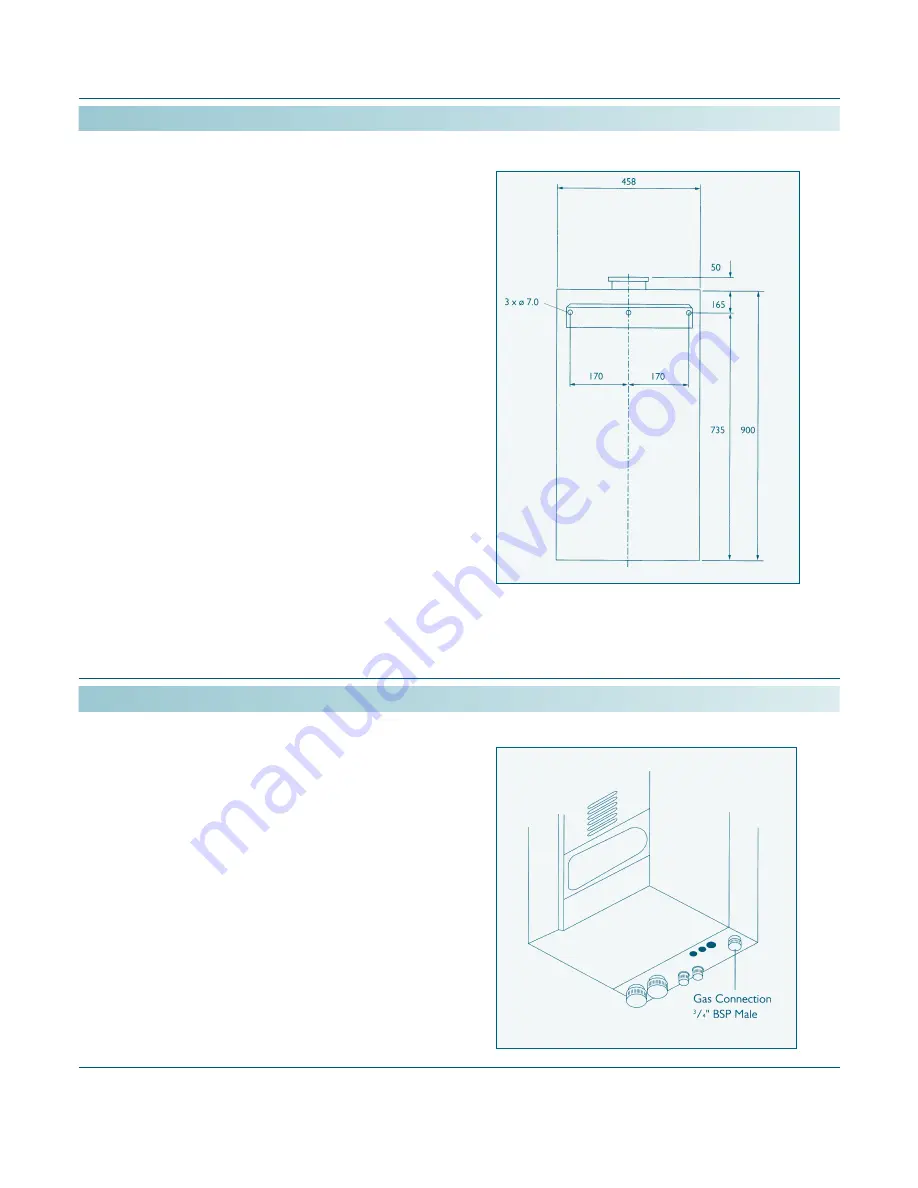
8.0 wall
mounting
fig. 1
fig. 2
The MICROMAT EC boiler mounts to the wall via a
wall mounting bracket which interlocks to a rail on the
rear of the boiler. The wall mounting bracket should be
firmly fixed to the wall using suitable fixings with a
countersunk head. The wall mounting bracket positioning
detail is shown in fig 1. The boiler must be carefully
offered up to the wall so that the rail on the rear of the
boiler is just above the wall mounting bracket and then
the boiler should be lowered to engage the bracket and
rail. Lifting is advised with 2 persons.
Do NOT lift the
boiler by the internal parts of the appliance.
important
When viewed from the side, the axis of the boiler must
be vertical. The appliance must not be inclined out from
the top, if necessary block or shim behind the bottom
rear of the boiler to achieve a vertical installation.
The gas connection is located at the base of the
appliance rear r/h side, see fig 2. The pipe size used
to supply the appliance must not be smaller than the
gas connection size on the appliance. The connection
to the appliance must include a suitable method of
disconnection and a gas control cock must be installed
adjacent to the appliance for isolation purposes. The
gas pipe used to supply the appliance must not allow
a pressure drop of greater than 1mbar from the meter
to the appliance. The nominal inlet working gas pressure
measured at the appliance should be 20.0 mbar for
Nat. Gas and 37 mbar for LPG.
Содержание MICROMAT EC 45
Страница 1: ......
Страница 2: ......
Страница 32: ...32 17 0 electrical connections E n e r g y T e c h n o l o g y Ltd plan of internal electrical connections ...
Страница 43: ...43 18 2 dipswitch settings E n e r g y T e c h n o l o g y Ltd ...
Страница 46: ...46 18 4 setting weather compensation E n e r g y T e c h n o l o g y Ltd ...
Страница 47: ...47 18 4 setting weather compensation E n e r g y T e c h n o l o g y Ltd ...
Страница 56: ......