


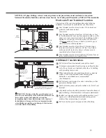


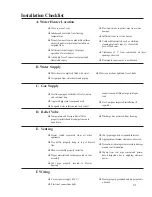

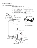


Typical Piping Diagram for Combination Potable/Space Heating Installation
Spring loaded check valve in heating unit
hot water supply line and cold water return
line (not supplied with water heater)
NOTE: This check valve is incorporated
in some heating units. Refer to the
installation instructions supplied with
specific heating unit to determine if it is
required.
All water piping shall be insulated in
accordance with Local and State Energy
Code.
Isolation valve in
cold water return line
from heating unit (not
supplied with water
heater)
Nominal 3/4" size mixing or tempering valve
(refer to warning above). Follow mixing or
tempering valve manufacturer’s instructions for
installation of the valve.
Temperature and pressure relief
valve discharge line
Air Handler
Drain valve
(not supplied with
water heater)
Hot water
to space heater
Temperature and Pressure Relief
Valve, tie to location approved by
local code
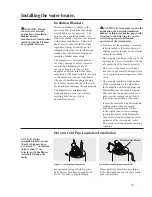
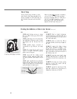
See diagrams above for proper
pipe application for vertical
or horizontal supply lines.
Isolation valve in hot water supply line
to heating unit (not supplied with water
heater)
3/4" cold water supply
3/4" Tempered
domestic hot water
supply to house.
Gas line to water heater
6” Air Gap
Combustion Air Inlet
Openings
2 Gallon Thermal
Expansion Tank (if
required-not supplied
with water heater)
Air vent
Heat Trap
6” Min.
3/4" Shut-Off Valve (Typ.)
3/4" Check Valve with 1/8" Hole
Pressure Gauge
3/4" Shut-Off Valve (Typ.)
3/4" Shut-
Off Valve
(Typ.)
Hot water coil
All bronze pump.
Check valve
internal in pump.
Air bleed valve.
Water Sample Tap.
T
FAN
ON
OFF
HEAT
COOL
To HVAC Unit.
Electronically controlled pump timer.
Activates every 6 hours for 60 seconds.
Wire to bronze pump.
3/4" HWS & HWR
to Heating Coil.
Minimum of 2'-0" developed length
of 3/4" pipe.
Water Heater drain pan installed in
accordance with the Local and State
Code
Water Heater to be in accordance with
the Local and State Energy Code
Gas Fired
Water Heater
Gas Direct Vent discharge
must comply with Local
and State Codes
Vacuum Relief Valve
(Not Supplied)
If required, install per local codes
and valve manufacturer’s
instructions.
120° to 130°
140°
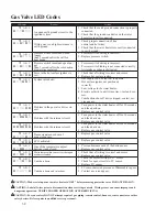
23
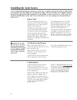
Lighting the water heater.
Before operating this water heater, be sure to read and follow the instructions on the label pictured
below and all other labels on the water heater, as well as the warnings printed in this manual. Failure
to do so can result in unsafe operation of the water heater resulting in property damage, personal
injury, or death. Should you have any problems reading or following the instructions in this manual,
STOP, and get help from a qualified person.
FOR YOUR SAFETY READ BEFORE OPERATING
WARNING: If you do not follow these instructions and use the Use & Care Manual instructions
exactly, a fire or explosion may result causing property damage, personal injury or loss of life.
OPERATING INSTRUCTIONS
AX 4762
TO TURN OFF GAS TO APPLIANCE
If you cannot reach your gas supplier, call
the fire department.
C.
Do not use this appliance if any part has been
under water. Immediately call a qualified in-
staller or service agency to replace a flooded
water heater. Do not attempt to repair the unit!
It must be replaced!
Use only your hand to push in the gas control
buttons. Never use tools. If the control buttons
will not push in, don’t try to repair them, call a
qualified service technician. Force or attempted
repair may result in fire or explosion.
D.
instructions.
This appliance does not have a pilot. It is equipped
with an ignition device which automatically lights
the burner.
Do NOT try to light the burner by hand.
A.
BEFORE PUTTING THIS APPLIANCE INTO
SERVICE - Smell all around the appliance
area for gas. Be sure to smell next to the floor
because some gas is heavier than air and
B.
will settle on the floor.
Immediately call your gas supplier from a
neighbor’s phone. Follow the gas suppliers
Do not try to light any appliance.
Do not touch any electric switch; do not use
any phone in your building.
WHAT TO DO IF YOU SMELL GAS
9.
10.
Stop! Read the safety information above on
this label.
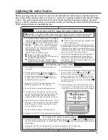
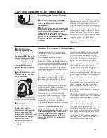
Set the thermostat to the lowest setting by
pressing the COOLER or HOTTER buttons
at the same time and holding them for (1)
second. Depress the COOLER button until
the WARM indicator light is lit.
Toggle the “ON/OFF” switch located on the
blower assembly to the “OFF” position.
Turn off all electric power to the appliance.
This appliance is equipped with a Hot Surface
Ignition System which automatically lights the
burner.
Do NOT open the inner door of this
appliance and try to light the burner by hand!
Wait five (5) minutes to clear out any gas. If you
smell gas, STOP! Follow “B” in the safety inform-
ation above on this label. If you do not smell
gas, go to the next step.
Turn on all electric power to the appliance.
Toggle the “ON/OFF” switch located on the blower
1.
3.
2.
1.
2.
3.
4.
5.
6.
7.
8.
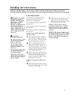
MANUAL
VALVE
TEMPERATURE DIAL
LED INDICATOR LIGHT
VACATION
WARNING
VERY
HOT
WARM
A
B
C
COOLER
HOTTER
assembly to the “ON” position.
Set thermostat to the desired temperature setting
by pressing the COOLER and HOTTER
buttons at the same time and holding them for (1)
second. Depress the HOTTER button until the
desired temperature is/are lit. The preferred start-
ing point for temperature setting is indicated by
on the thermostat.
If the appliance will not operated, follow the
instructions “TO TURN OFF GAS TO APPLIANCE”
and call your service technician or gas supplier.
Turn off all electric power to the appliance if service is to be performed.
Set the thermostat to the lowest setting by first depressing the COOLER and HOTTER buttons at
the same time and holding for 1 second. Depress the COOLER button until only the WARM indicator
light appears.
Toggle the “ON/OFF” switch located on the blower assembly to the “OFF” position.
Содержание PowerVent AP14236
Страница 34: ...34 Notes...
Страница 35: ...35 Notes...