background image


Wählen Sie den Montageort so, dass die 

Funktion des Patchpanels z. B. durch 

Spritzwasser nicht beeinträchtigt werden 

kann. Bitte achten Sie für eine störungs-

freie Funktion bei der Auswahl des Patch-

kabels auf eine normgerechte Ausführung 

der Stecker (gemäß IEC 60603-7-x).

Montage des Gehäuses

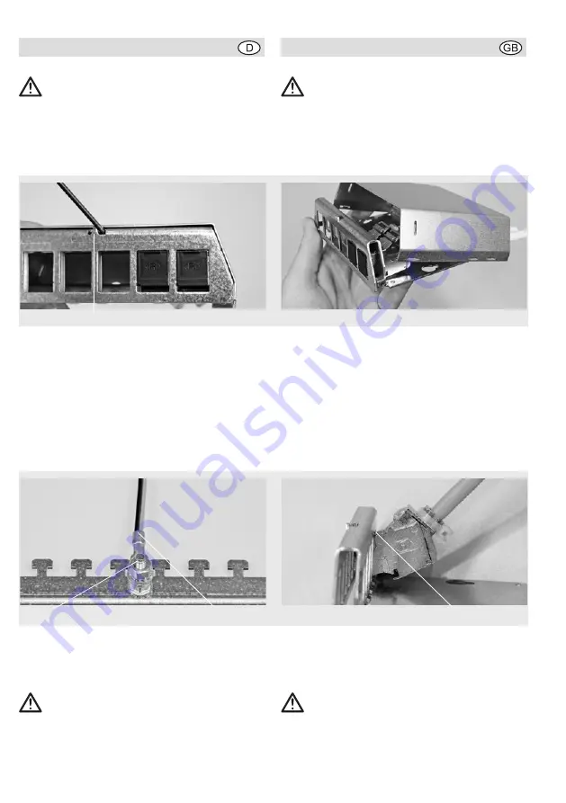
Lösen Sie den Gehäusedeckel von der Träger-

platte, indem Sie diesen, z. B. mit einem dünnen 

Schraubendreher, über die Rastnase (A) hebeln.

Ziehen Sie dann den Gehäusedeckel vorsichtig, 

ohne zu Verkanten, nach hinten und oben ab.

Für die Montage an der Wand steht im Anhang 

eine Bohrschablone zur Verfügung. Für die Mon-

tage auf einer DIN-Normschiene verwenden Sie 

die Hutschienenadapter 221 012.

Erdung

Befestigen Sie den mitgelieferten Schutzleiter (C) 

am Gewindebolzen (B) der Trägerplatte unbedingt 

vor dem Anlegen der Adpter! 


Verbinden Sie die Gehäuseerdung norm-

gerecht mit der passenden Erdungsstelle.

Modul einsetzen

Führen Sie das konfektionierte Modul von hinten 

heran. Haken Sie das Modul mit der Rastnase (D) 


Choose the installation location so that the 

function of the patch panel will not be 

impaired (by splashing water, for example). 

Make sure to select a patch cable with a 

connector designed according to stand-

ards (i.e. according to IEC 60603-7-x) to 

ensure trouble-free operation.

Mounting the housing

Remove the housing cover from the base plate by 

releasing the retaining tab (A) using a small screw-

driver, for example. Now carefully pull the housing 

cover towards the back and up without tilting it to 

one side. 

There is a drilling template available in the appen-

dix for wall mounting. For installation on a standard 

DIN rail, use the top hat rail adapter 221 012.

Grounding

Make sure to fasten the ground conductor (C) 

supplied to the threaded bolt (B) of the base plate 

before connecting the adapter! 


Connect the housing ground to an appro-

priate grounding point according to the 

standards.

Inserting modules

You insert the connected modules from the back. 

Hook the retaining tab (D) of the module behind 

Installation 

Installation 

2

A

B

C

D

Содержание PP-UM A 6 Ap

Страница 1: ...e patch panel offers enough space for the sim ple installation of a maximum of 6 UM Cat univer sal modules or KMK communication adapters and is made of a stable fully shielded metal housing It also contains the ground connection straps for fastening the cables and recesses in the housing for wall mounting Modules can also be added at any time after installation The housing is suitable for wall mou...

Страница 2: ... das konfektionierte Modul von hinten heran Haken Sie das Modul mit der Rastnase D Choose the installation location so that the function of the patch panel will not be impaired by splashing water for example Make sure to select a patch cable with a connector designed according to stand ards i e according to IEC 60603 7 x to ensure trouble free operation Mounting the housing Remove the housing cove...

Страница 3: ...rwendung nicht normgerechter Anschluss komponenten müssen wir von einer Anerkennung the face plate of the base and push down to click it in place Fastening the cables Take the length of the data cables into account when choosing the final installation location Fas ten each cable in place separately using cable ties E for example Removing modules Insert the screwdriver from the bottom in the mid dl...

Страница 4: ...en darf sondern in dafür ausgerüsteten Sammelzentren zur sachgemäßen Wiederverwendung bzw Entsorgung abzugeben ist if connector components not conforming to the standards are used Please inform the end users of this fact You should also avoid unnecessary mechanical strain on the jacks when plugging or unplugging patch cables due to pulling or pressing on the connector or inserting them incorrectly...

Страница 5: ...UM A 6 Ap Der Abstand beim Patchpanel PP UM A 12 Ap beträgt stattdessen 222 mm The drilling template shown below is for the PP UM A 6 Ap patch panel The distance between the holes for the PP UM A 12 Ap patch panel is 222 mm Bohrschablone Drilling template 113 mm 5 ...

Страница 6: ...ungssystems hergestellt wurde und sich in Übereinstimmung mit den Anforderungen und Vorschriften der Richtlinien 2004 108 EG und 2006 95 EG befindet Die vollständige Konformitätserklärung finden Sie unter www rutenbeck de im Downloadbereich We the Wilhelm Rutenbeck GmbH Co KG declare under our sole responsibility that the patch panel was manufactured according to a certified comprehensive quality ...

Отзывы: