37
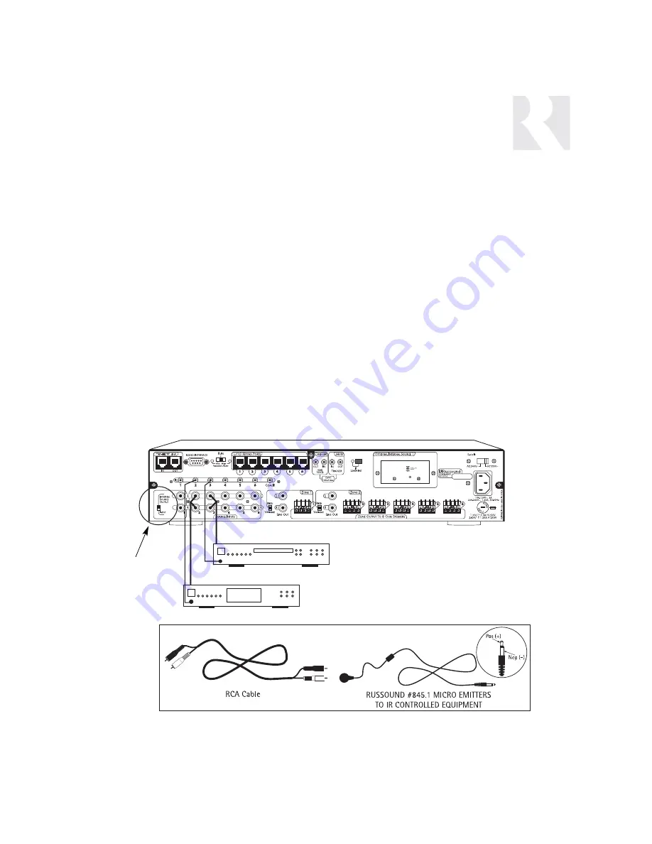
Source Audio Connections
The CAM6.6 supports up to six audio sources.
The Source Inputs are located at the back panel.
The Source 1 input serves a dual purpose. If the
CAM6.6 optional internal source is used, the
Source 1 inputs are not available, and the switch
next to it is set to “Internal Source Output.” If the
Optional Internal Source is not installed, or if you
want to utilize the Source 1 inputs, set the switch
to “Input” and reconfigure Source 1 in the Source
Setup Menu. Connect each source output using
quality RCA signal cables. Connect the Left and
Right Audio outputs from each source to the cor-
responding inputs on the CAM6.6 controller. Label
each cable with the name of the selected source
and the Source Audio input number located on
the CAM6.6.
Source IR Connections
Each source component has a designated IR
port on the back of the CAM6.6. This IR port is
directly above the Source Audio Input
Connections.
1. Using an IR emitter (the Russound 845.1 is
recommended), attach the end of the emitter
with the 1/8
”
plug to the IR emitter port above
the source input.
2. Remove the adhesive back at the other end
of the emitter and attach the emitter over the
source component’s IR window.
3. In order to control this source component
with IR, the source must be selected at the
keypad receiving the command.
CAM6.6
A
NTENNA
Tape Player
CD Changer
INSTALLER
MAKING CONNECTIONS
Source Audio and IR Input Connections
Use the source 1
output/input switch
for audio out of the
optional internal
source or audio in
of connected
source equipment.
CAM6.6 with Optional Internal Source - XM satellite radio
Содержание CAM6.6X
Страница 1: ...CAM6 6X S1 S2 System 6 Zone 6 Source XM Receiver and UNO Smart Keypads INSTRUCTION MANUAL ...
Страница 49: ...49 XM Russound N A Peripheral N A N N A N N A N A INSTALLER SETUP FORMS ...
Страница 50: ...50 Mute INSTALLER SETUP FORMS ...
Страница 51: ...51 INSTALLER SETUP FORMS ...
Страница 69: ...69 INSTALLER SETUP MENU FLOW CHARTS PERIPH SETUP Menu Peripheral ...
Страница 70: ...70 INSTALLER SETUP MENU FLOW CHARTS PERIPH SETUP Menu ...
Страница 71: ...71 PERIPH SETUP Menu INSTALLER SETUP MENU FLOW CHARTS ...
Страница 72: ...72 PERIPH SETUP Menu INSTALLER SETUP MENU FLOW CHARTS ...
Страница 73: ...73 PERIPH SETUP Menu INSTALLER SETUP MENU FLOW CHARTS ...
Страница 74: ...74 INSTALLER SETUP MENU FLOW CHARTS PERIPH SETUP Menu MUTE ...
Страница 75: ...75 PERIPH SETUP Menu INSTALLER SETUP MENU FLOW CHARTS ...
Страница 76: ...76 INSTALLER SETUP MENU FLOW CHARTS PERIPH SETUP Menu ...
Страница 77: ...77 PERIPH SETUP Menu LED on rear CAM Panel blinks fast INSTALLER SETUP MENU FLOW CHARTS ...
Страница 78: ...78 INSTALLER SETUP MENU FLOW CHARTS PERIPH SETUP Menu ...
Страница 79: ...79 PERIPH SETUP Menu INSTALLER SETUP MENU FLOW CHARTS ...
Страница 113: ...113 NOTES ...
Страница 114: ...114 NOTES ...
Страница 115: ...115 NOTES ...


