40
Deploying the Access Point
Step 3: Connect the Access Point to the Network
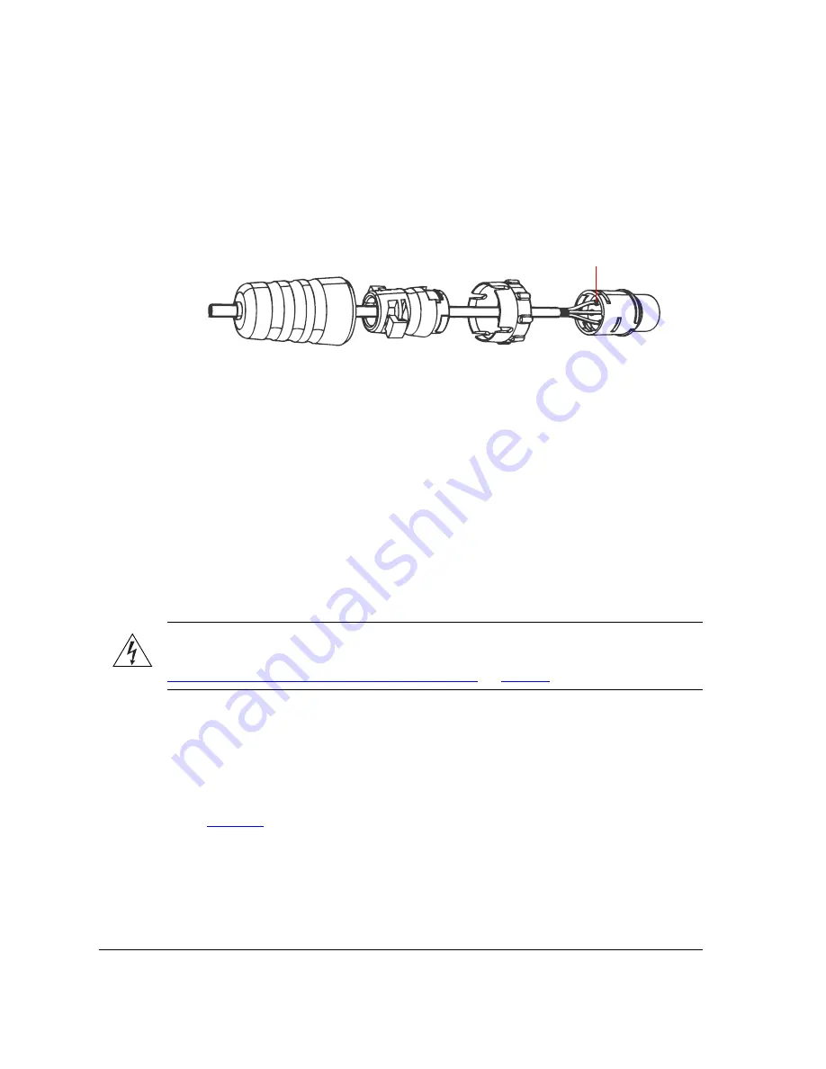
Figure 32.
Insert the conductors into the pins, crimp or solder the edges, and then
insert the pins into the connector
7.
Push the coupling ring all the way forward so that it covers the edge of the cord
connector.
8.
Push the cable clamp housing forward until it locks into the connector body. The two
clamps should snap into their compartments.
9.
Push the boot all the way forward so that it covers the cable clamp housing securely.
10.
Remove the protective cap from the 12V DC connector on the AP.
11.
Connect the DC cord connector that you have assembled to the 12V DC connector on
the AP.
12.
Connect the DC cable to a DC power source (for example, a battery).
You have completed connecting the Access Point to the administrative computer and to
a DC power source.
WARNING:
Do not apply power to the Access Point at this point. You should connect the
Access Point to a power source only after you finish connecting all other components in
“Step 3: Connect the Access Point to the Network”
on
page 40
.
You have completed setting up the DC power connection.
Step 3: Connect the Access Point to the Network
In this step, you will connect the Access Point from its mounting location to the network.
The connections required for your installation depend on the power sources that you are
using.
Figure 33
shows an example of the connections required for a typical installation
that uses both PoE and DC power as power sources.
Crimp or solder the conductors
before inserting them into the
connector
Содержание ZoneFlex 7762-T
Страница 2: ......
Страница 62: ...58 What to Do Next Read Related Documentation...