17
A
A
B
B
A-A
B-B
1
2
3
3
4
EN
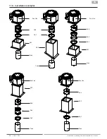
14.2. Impeller installation with Taperlock clamping bush
1. Clean all bare surfaces (mating surfaces of
the clamping bushings and motor shaft).
2. Insert the clamping bush (1) into the hub (2)
and bring the holes into alignment.
3. Loosely lubricate the threaded pins (3) and
screw in - do not tighten yet.
4. Push the impeller onto the shaft with the
clamping sleeve, align it in the axial position
and tighten the threaded pins evenly on both
sides. Observe the tightening torque accor-
ding to table.
Assembly
The impeller is connected by means of the clamping bush to the shaft end of the drive motor.
Disassembly
1. Loosen all the threaded studs (3) and screw
them out completely. Lubricate a threaded
pin and screw it into the disassembly hole
(4).
2. Tighten the threaded pin until the clamping
bush (1) is released from the hub (2).
3. The impeller can be removed.
Bushing size
Torque table
Bushing size
1210
2012
2517
Screw tightening torque with feather
(Nm)
17
26
41
Screw tightening torque without feather
(Nm)
20
31
48
Number of screws
2
2
2
Technical data
Commissioning (after replacement)
■
Remove any remaining installation material and foreign objects from the impeller and suction area.
■
Check direction of rotation (direction of rotation arrow on the impeller base disc).
■
During initial commissioning, the entire unit must be checked for mechanical vibrations. If necessary, re-balancing
must be carried out.
■
Pay attention to a quiet operation, without vibrations.
www.ruck.eu |
Содержание DVN***D.F4 Series
Страница 19: ...19 EN Notes www ruck eu...


