


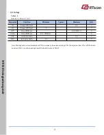


RT
21
4
In
te
gr
ati
on
gu
id
e
25
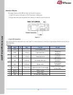
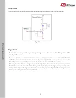
Beeper Circuit
The circuit below is used to drive an external beeper. The nBEEPER signal is from PIN 5 of the 13-pin FPC connector.
Figure 5-2
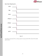
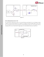
Trigger Circuit
The circuit below is used to provide the engine with a signal to trigger a scan and decode session. The nTRIG signal is from PIN 2
of the 13-pin FPC connector.
The host can adjust the external circuit and its functions based on actual applications. R1 is recommended as 10K-100K and R2
as 33
Ω
. C1 is used to eliminate the vibration of mechanical keys. Generally, 1nF-10nF ceramic capacitors are recommended.
When ESD protection is required, ESD protector can be added to the external circuit like ED1 shown as below.
When using the external IO port as a trigger output, note that high and low levels must meet the requirements provided in
Table 3-3. It is recommended to use the default floating or default pull-up IO port as the trigger pin. If you can only use the
default pull-down IO port as the trigger pin, refer to the power-on timing sequence in Figure 3-5. When not triggered, ensure
that the pin meets the high level requirements inTable 3-3.


