


23
RT
21
4
In
te
gr
ati
on
gu
id
e
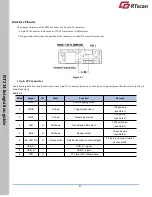
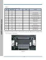
Table 4-2
12-pin connector (Pin definition of pinout of RT214 )
PIN#
Signal Name
I/O
State
Function
1
NC
-
-
-
2
VDD
-
-
3.3V power input
3
GND
-
-
Power-supply ground
4
RXD
I
-
TTL level 232 receive data
5
TXD
O
-
TTL level 232 transmit data
6
USB_D-
-
-
USB_D- signal
7
USB_D+
-
-
USB_D+ signal
8
NC
-
-
-
9
BUZ
O
-
Beeper output
10
LED
O
-
Good Read LED output
11
nRST
I
-
Reset signal input
12
nTRIG
I
-
Trigger signal input
Note: please remember your device’s TXD should be connected to RXD of RT214, and RXD to TXD.
The 12-PIN connector is shown as below.
Figure 4-2


