


21
RT
21
4
In
te
gr
ati
on
gu
id
e
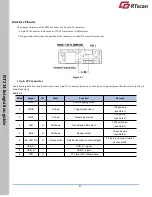
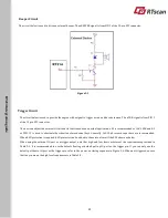
Interface Pinouts
The physical interface of the RT214 consists of a 13-pin FPC connector:
•
13-pin FPC connector can be used as TTL-232 interface or USB interface.
The figure below illustrates the position of the connector on the RT214, as well as the pin 1
.
13-pin FPC Connector
Figure 4-1
The following table lists the pin functions of the 13-pin FPC connector (if you don
’
t use 13pin out, please ignore this and refer to the 12-pin
definition below).
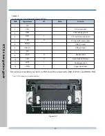
Table 4-1
PIN#
Signal
I/O
State
Function
Remark
1
GND
-
-
Power-supply ground
2
nTRIG
I
Pull-up
Trigger signal input
100k pull-up
(see Note 1)
3
nRST
I
Pull-up
Reset signal input
4.7k pull-up
(see Note 2)
4
LED
O
Pull-down
Good Read LED output
100k pull-down
(see Note 3)
5
BUZ
O
Pull-down
Beeper output
10k pull-down
(see Note 4)
6
Ext.LED.Crtl
O
Unconnected
External illumination control signal
If the pin is not used, leave it
unconnected.
7
USB_D+
-
-
USB_D+ signal
8
USB_D-
-
-
USB_D- signal
9
TXD
O
-
TTL level 232 transmit data


