


13
RT
21
4
In
te
gr
ati
on
gu
id
e
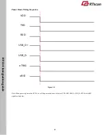
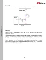
Power Supply
Do not power up the RT214 until it is properly connected. Be sure the power is cut off before connecting a cable to or
disconnecting a cable from the host interface connector. Hot-plugging could damage the engine.
Unstable power supply or sharp voltage drops or unreasonably short interval between power-ons may lead to unstable
performance of the engine. Do not resupply the power immediately after cutting it off.
※
When designing, the user should ensure that the input power of RT214 is fully decoupled. It is recommended to place a
22uF and a 100nF X5R or X7R ceramic capacitor beside the power input pin on the connector which is soldered on the board.
The capacitor mounted on the external input power supply is recommended to be controlled within 50uF.
※
Ensure that the input power drops below 0.5V before powering the RT214 on again, otherwise it will lead to abnormal
function.
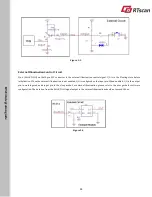
Ripple Noise
To ensure the image quality, a power supply with low ripple noise is needed. Acceptable
ripple range (peak-to-peak) :≤100mV
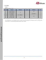
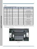
DC Characteristics
Operating Voltage
Table 3-1
T=25°C
Parameter
Description
Minimum
Typical
Maximum
Unit
VDD
Input Voltage
3.14
3.3
3.47
V
Operating Current
Table 3-2
T=25
°
C
Description
State
PEAK
RMS
Unit
Working Current
VDD=3.3V
240
138
mA
Standby Current
-
11.8
mA


