background image

3R60

User Manual

szruitech.com

5

3.4 Control signal connection

3.4.1 PUL, DIR port: connection for pulse command

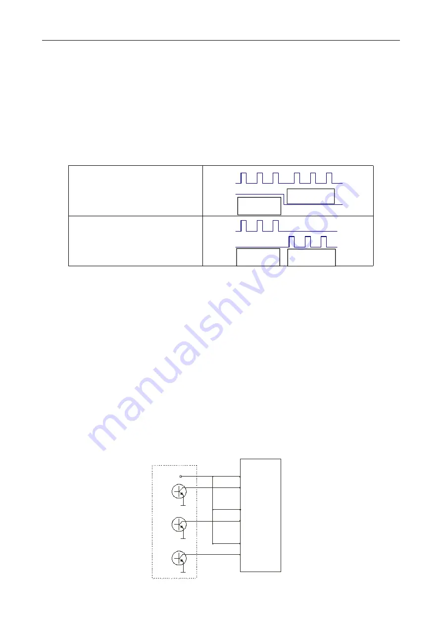
The standard R series driver signal interface is in the form of pulse, and 3R60 can receive two kinds of
pulse command signals.

The upper controller can be the pulse signal generating device, such as PLC, MCU, control card and
controller.

The pulse level that 3R60 driver can be used: 3.3V-24V (

no need to connect resistor

)

Pulse and direction (PUL + DIR)

Double pulse (CW +CCW)

3.4.2 ENA port: used to enable or disable

When the internal optocoupler is off, the driver outputs current to the motor;

When the internal optocoupler is on, the driver will cut off the current of each phase of the motor to make
the motor free, and the step pulse will not be responded.

When the motor is in error state, ENA input can be used to restart the driver. Firstly, the fault is eliminated,
and then a falling edge signal is input to the ENA terminal. The driver can restart the power part and the
motor is excited.

The level logic of the ENA signal can be set to the opposite, with the logic being opposite to the above.

3.4.3 Examples for control signal connection

Common Anode

Pul+

Pul-

Dir+

Dir-

Ena+

Ena-


Vcc

Forward

Forward

Reverse

Reverse

Содержание Ruitech 3R60

Страница 1: ...3R60 User Manual szruitech com 3 Phase Stepper Motor Driver 3R60 User Manual Shenzhen Rtelligent Mechanical Electrical Technology Co ltd...

Страница 2: ...Port function description 3 3 2Power supply input 3 3 3Motor connection 4 3 4Control signal connection 5 3 4 1 PUL DIR port connection for pulse command 5 3 4 2 ENA port used to enable or disable 5 3...

Страница 3: ...and 8 current selections It has overvoltage undervoltage and overcurrent protection Its input and output control signals are optically isolated Power supply 24 50VDC Output current DIP switch setting...

Страница 4: ...nt 3R60 Installation environment Avoid dust oil and corrosive environment Vibration 0 5G 4 9m s2 Max Operating temperature humidity 0 45 90 RH or less no condensation Storage and transportation temper...

Страница 5: ...ans to ensure good heat dissipation conditions in the control cabinet 3 Driver port and connection 3 1 Port function description Function Grade Definition Remarks Power supply input port V Input DC po...

Страница 6: ...current at both ends of the motor winding In actual use the appropriate power supply should be selected according to the motor model load torque and other factors The effects of regeneration voltage W...

Страница 7: ...or disable When the internal optocoupler is off the driver outputs current to the motor When the internal optocoupler is on the driver will cut off the current of each phase of the motor to make the m...

Страница 8: ...Pul Dir Dir Ena Ena Vcc Vcc Difference Pul Pul Dir Dir Ena Ena Pul Pul Dir Dir Ena Ena 4 The setting of DIP switches and operating parameters The setting of current The setting of pulse per revolution...

Страница 9: ...If you don t need the motor running continuous you can increase the current to higher the torque But be minded that the current can not be 1 5times over than the rated current 4 2 The setting of puls...

Страница 10: ...is flickering Driver working normally One green indicator and one red indicator Driver overcurrent One green indicator and two red indicators Driver input power overvoltage One green indicator and thr...

Страница 11: ...of Pulse per revolution is wrong Check the DIP switch status and correctly connect the switches Encoder signal is abnormal Replace the motor and contact the manufacturer The driver terminal burned up...

Страница 12: ...reversed and insert pull the motor connection when the power supply is connected Beyond electrical and environmental requirements Change the internal device without permission 7 3 Maintenance process...

Отзывы: