RTD Embedded Technologies, Inc.
|
www.rtd.com
17
ERES35105
User’s Manual
4.4.1
E
XTERNAL
I/O
C
ONNECTORS
Sensor Input / Output
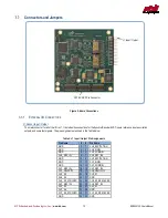
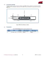
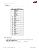
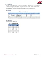
The IDAN connector includes the connections for the Synchro/Resolver/LVDT inputs, reference inputs, excitation outputs, and some test
signals. The pin assignments are shown in the Table below.
Table 6: IDAN Input / Output Pin Assignments
IDAN Pin #
Pin Name
J1 Pin #
1
CH0_EXCITATION
1
2
C
3
3
CH0
5
4
CH0
7
5
CH1_EXCITATION
9
6
C
11
7
CH1
13
8
CH1
15
9
CH0_VELOCITY
17
10
CH0_S1
19
11
GND
21
12
CH0_S2_RESOLVER
23
13
CH0
25
14
CH1_S1
27
15
GND
29
16
CH1_S2_RESOLVER
31
17
GND
33
18
RESERVED
-
19
RESERVED
-
20
GND
2
21
GND
4
22
GND
6
23
CH0_REF_IN-
8
24
GND
10
25
GND
12
26
GND
14
27
CH1_REF_IN-
16
28
CH1_VELOCITY
18
29
CH0_S3
20
30
CH0_S4
22
31
CH0_S2_SYNCHRO
24
32
CH1
26
33
CH1_S3
28
34
CH1_S4
30
35
CH1_S2_SYNCHRO
32
36
GND
34
37
RESERVED
-
4.4.2
B
US
C
ONNECTORS
CN1 (Top) & CN2 (Bottom): PCIe Connector
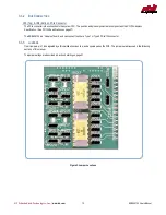
The PCIe connector is the connection to the system CPU. The position and pin assignments are compliant with the
PCI/104-Express
Specification
. (See PC/104 Specifications on page 37)
The ERES35105
is a “Universal” board, and can connect to either a Type 1 or Type 2 PCIe/104 connector.


