RST DT2350 Скачать руководство пользователя страница 14


DT2350 2-Channel Strain Gauge 

 Load Cell Data Logger Manual 


ELM0099A 

RST Instruments Ltd. 

Page 10  


T

ABLE 

4-1


L

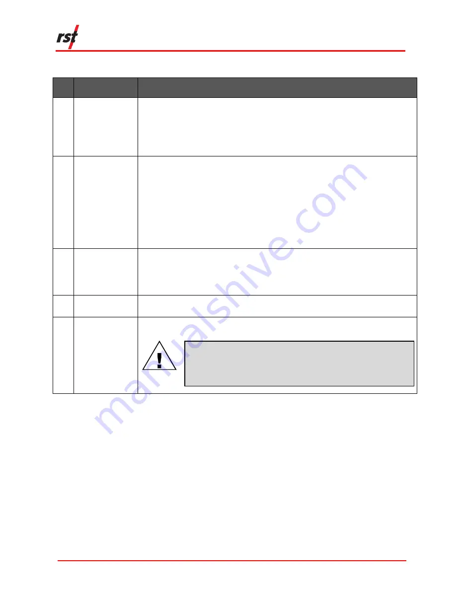
OGGING TAB OPTIONS AND DESCRIPTION


Setting 

Application 

Interval 

Select 'Use Fixed Interval' to adjust the intervals and set the logging frequency. 
Select 'Use Multi Interval Table' and click on ‘Multi Interval’ to set up to 12 custom, multiple 
logging frequencies.  

Note

: The hour, minute, second, and number of iterations per interval must be specified. 

Each interval MUST have an iteration except the last iteration which must be set to zero. 
This tells the program that the logger will continue at the last iteration rate. 

Logger Options  
(24 Hour Time) 

Check 'Use Start Time' to select the desired logging start time (24-hour format).  

Note

: The logger will not start until it reaches the custom start time even if the time has 

already passed. E.g., if the current time is 13:01 and the start time is set to 13:00, the 
logger will not start logging data until 13:00 the 

next day

. The status will read 

Log Pending


until the custom start time is reached. 

Select 'Wrap on Memory Full (Overwrite Data)' to overwrite the logger memory when 
logger memory is full.  

Select 'Stop Logging when Memory Full' to stop collecting data when logger memory is 
full. This option is recommended for locations with access issues where data may not be 
retrieved prior to battery failure.  

Clock Options 

Select a custom date and time or click 'Sync to computer date/time' to sync it to the 
computer’s current date and time. 
Select 'Auto sync date/time' to always sync to the computer’s date/time when connected 
via USB. 

Logger Label 

Type a custom name for the logger. Click 'Update Label' to apply the label.  
This name will appear in the data files. 

Apply Settings 

Click 'Apply Settings' to save any changes and upload them to logger memory. 'Apply 
Settings' 

must

 be clicked to ensure settings are saved. 


CAUTION: DATA LOSS WARNING  

A

LL EXISTING LOGGER DATA WILL BE ERASED DURING LOGGER SETTINGS 

UPLOAD

.


E

NSURE THE DATA HAS BEEN DOWNLOADED PRIOR TO APPLYING 

SETTINGS

.


S

ENSOR CONFIGURATION WILL NOT BE AFFECTED


Clicking ‘Apply Settings’ will display a prompt reminding the user to download 
existing logger data.  

Only click ‘yes’ if the data has already been downloaded. Click ‘no’ to return to the 
Logging Tab.  

4.2 

S

TATUS 

T

AB


View general information about the currently connected DT2350 data logger (such 
as logger information, logger status, battery life, and current memory usage) in the 
Status Tab (Figure 4-2).  

Содержание DT2350

Страница 1: ...9A All efforts have been made to ensure the accuracy and completeness of the information contained in this document RST Instruments Ltd reserves the right to change the information at any time and ass...

Страница 2: ...DT2350 2 Channel Strain Gauge Load Cell Data Logger Manual ELM0099A RST Instruments Ltd Page ii TABLE OF REVISIONS Rev Revision History Date Prepared By Approved By A Initial release 09 Apr 2019 MP JW...

Страница 3: ...d Materials 2 3 2 Software Installation 2 3 3 Load Cell Connection 3 4 LOGGER CONFIGURATION 8 4 1 Logging Tab 8 4 2 Status Tab 10 4 3 Data View Tab 11 4 4 Monitor Tab 12 4 4 1 Graphical Monitor 13 4 5...

Страница 4: ...ten screws in the following order and pattern 7 Figure 3 8 Mini B USB Port 7 Figure 3 9 Port and status indicators 8 Figure 4 1 The logging tab 9 Figure 4 2 The status tab 11 Figure 4 3 The data view...

Страница 5: ...1 DT2350 LOAD CELL DATA LOGGER A mini B USB connector cable and RST Resource DVD are included in a standard DT2350 data logger shipment Contact RST Instruments if any items are missing from the shipme...

Страница 6: ...ection 6 CAUTION DO NOT ATTEMPT TO RECHARGE THE BATTERY DO NOT REPLACE THE BATTERY WITH AN ALKALINE OR ZINC CARBON BATTERY DO NOT SHIP THE DT2350 DATA LOGGER WITH THE BATTERY INSIDE 3 INSTALLATION 3 1...

Страница 7: ...ABLE LOCATIONS THE LOGGER IS RAIN TIGHT ONLY AND NON SUBMERSIBLE NOTE THE PICTURES IN THIS SECTION ARE INSTRUCTIONAL AND MAY FEATURE A LOGGER OTHER THAN THE DT2350 TO ILLUSTRATE THE INSTRUCTIONS 1 Loo...

Страница 8: ...cable plug from the cable gland Refer to Figure 3 3 FIGURE 3 3 REMOVE THE CABLE PLUG FROM THE CABLE GLAND 3 Loosen the 4 Phillips screws on the top of the logger Lift the cover off 4 Insert the sensor...

Страница 9: ...ONS NOTE IGNORE PS AND PS TERMINALS WHEN CONNECTING THE 4 WIRE SENSORS TABLE 3 1 WIRING CHART FOR 4 AND 6 PIN CONNECTORS 4 Pin Connector Wires 6 Pin Connector A P Red A P B S Green B S C S White C S D...

Страница 10: ...THE CABLE GLAND COULD DAMAGE THE CABLE UNDER TIGHTENING THE CABLE GLAND COULD CAUSE A LEAKAGE AND WATER DAMAGE FIGURE 3 5 TIGHTEN THE CABLE GLAND 9 For a stand alone data logger insert the battery in...

Страница 11: ...ghten each screw in the X pattern as shown in Figure 3 7 Then securely tighten each screw in the X pattern FIGURE 3 7 TIGHTEN SCREWS IN THE FOLLOWING ORDER AND PATTERN CAUTION ENSURE THE DT LOGGER HOS...

Страница 12: ...50 is now ready to be configured for data logging 4 LOGGER CONFIGURATION The following sections detail how to correctly configure the DT2350 for data logging It is important to ensure the logger is pr...

Страница 13: ...Data Logger Manual ELM0099A RST Instruments Ltd Page 9 CAUTION DATA LOSS WARNING ENSURE THE DATA HAS BEEN DOWNLOADED PRIOR TO APPLYING SETTINGS ALL EXISTING LOGGER DATA WILL BE ERASED DURING LOGGER SE...

Страница 14: ...ger memory is full Select Stop Logging when Memory Full to stop collecting data when logger memory is full This option is recommended for locations with access issues where data may not be retrieved p...

Страница 15: ...appear asking to append or overwrite data Append will continue to add data to existing readings in the memory Overwrite data will erase all data in the logger and restart the logging process 4 3 DATA...

Страница 16: ...ain Gauge Load Cell Data Logger Manual ELM0099A RST Instruments Ltd Page 12 FIGURE 4 3 THE DATA VIEW TAB 4 4 MONITOR TAB The following section details the features of the Monitor Tab Figure 4 4 FIGURE...

Страница 17: ...s when successfully connected to the data logger A green indicator will flash each time a sensor data is updated The program will display in each Sensor Reading field until communication is establishe...

Страница 18: ...gs dialog and manipulate graph properties such as line style background color and grid lines 4 5 SENSOR TAB The Sensors tab shows current sensor configurations Figure 4 6 Readings are reported in mV V...

Страница 19: ...cer elevation Display Format Click to customize monitor display settings Upload to Logger Click to update logger with current sensor settings Note Upload to Logger must be clicked to update logger wit...

Страница 20: ...ncy and downloads folder location 5 TROUBLESHOOTING Press F1 or click the help button to activate the help system Answers to common problems and troubleshooting tips may be found by browsing help topi...

Страница 21: ...or two SAFT LS 14500 AA batteries or equivalent Compact battery options are designed to support the same level of performance in the DT 2350 and are considered equivalent TABLE 6 1 BATTERY TYPES Batt...

Страница 22: ...estimated battery life is 20 or less 6 3 CHANGING THE BATTERY The following steps outline the procedure to change the battery CAUTION CONNECT THE DATA LOGGER TO THE DT LOGGER HOST SOFTWARE AND RE APPL...

Страница 23: ...nnections Tab Click on Advanced Click on Initialize Battery 7 Click on the Logging Tab Verify that the settings are correct Click on Apply Settings to verify any parameter changes or to ensure current...

Отзывы: