


Documenting Multifunction Calibrator / EN
54
06/04/2018 Version No. 1
(
Appendix 1
)
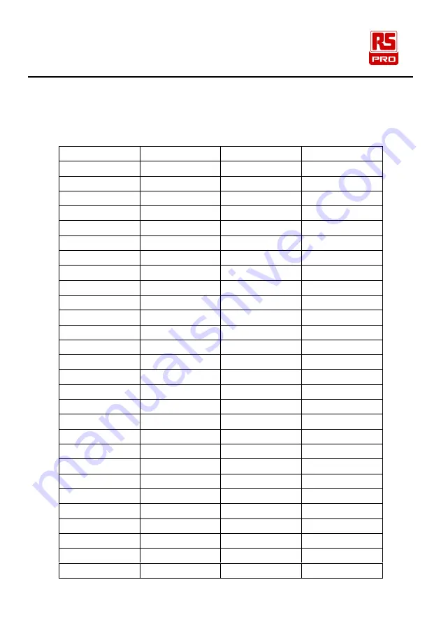
ASCII code list
Decimal System
ASCII
Decimal System
ASCII
32
62
>
33
!
63
?
34
"
64
@
35
#
65
A
36
$
66
B
37
%
67
C
38
&
68
D
39
'
69
E
40
(
70
F
41
)
71
G
42
*
72
H
43
+
73
I
44
,
74
J
45
-
75
K
46
.
76
L
47
/
77
M
48
0
78
N
49
1
79
O
50
2
80
P
51
3
81
Q
52
4
82
R
53
5
83
S
54
6
84
T
55
7
85
U
56
8
86
V
57
9
87
W
58
:
88
X
59
;
89
Y
Содержание RS-133
Страница 1: ...Instruction Manual RS 133 Documenting Multifunction Calibrator Arbitrary Function Generator ...
Страница 40: ...Documenting Multifunction Calibrator EN 34 06 04 2018 Version No 1 Connecting Leads for Multi step Scanning ...
Страница 44: ...Documenting Multifunction Calibrator EN 38 06 04 2018 Version No 1 Connecting Leads for Multi step Scanning ...
Страница 48: ...Documenting Multifunction Calibrator EN 42 06 04 2018 Version No 1 Connecting Leads for Multi step Scanning ...


