PLASTIC MOULDINGS
V
IA DELL
’
ARTIGIANATO
,
6
•
61026
LUNANO
(PU)
•
I
TALY
T
EL
.
+39
0722
722801
•
F
AX
+39
0722
70599
•
W
EB
:
www.rototec.it
E-
:
•
PEC
VAT
and TAX
CODE
01476690415
•
C
OMPANY
C
APITAL
.
120.000,00
CCIAA
(C
HAMBER OF
C
OMMERCE
R
EG
.
N.)
12602
P
ESARO
DEPURO ONE Use and Maintenance Manual, Rev. 00 of 27/01/2016
Page 6 of 13
6. INSTALLATION
Tanks
•
Before installing the tanks, make sure that all the components are present: primary sedimentation tank and
oxidation tank with recirculation. Both tanks are fitted with biogas vents. The oxidation tank has a pair of diffuser
pipes installed internally. Two blowers and an electric blower control panel are supplied in 3 separate boxes.
•
The tank installation sequence is that indicated in the installation diagram (see Paragraph 5)
•
It’s advisable to install the tanks making up the plant no more than one metre apart. The distance between the
tanks can be greater providing that the connecting pipe has a gradient of not less than 2%.
•
When installing the tanks, the pipes should always have a gradient of 2-3%.
•
Connect the sludge recirculation pipe between the two tanks.
•
To prevent bad smells from being generated during plant operation, always connect the biogas vents of both
tanks to a suitable pipe discharging to atmosphere, preferably on the roof of the building.
Install the tanks scrupulously following the installation instructions supplied by ROTOTEC (Paragraph 9). DEPURO
ONE plants must always be installed underground.
Blowers/compressors
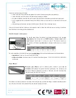
Diaphragm type air compressors used in air-lift sludge return systems and for developing an
aeration system necessary for the digestive processes of the aerobic bacteria, making use of the
electromagnetic vibration of an actuator rod supported by synthetic rubber diaphragms.
The blowers, together with the electric control panel, must be installed in an appropriate covered control room prepared
by qualified personnel. The room must have the following characteristics:
•
it must be positioned above ground at a maximum distance of 10 m from the treatment plant;
•
the base must be solid, flat and located above the level of the tank in order to avoid a backflow of sludge in the
case of an interruption in the air supply;
•
it must have sufficient air changes to prevent the blower from overheating and to allow the entry of the air
required to pump into the tanks;
•
the internal environment must be free of corrosive gases and must not be exposed to vibration.
Model
Voltage
V
Frequency
Hz
Watt
W
Amps
A
Capacity
l/min
Rated
Pressure bar
Noise level
dB
Weight
Kg
Length
mm
Width
mm
Height
mm
HP 40
220
50
31
0,32
40
0,130
< 39
4,9
260
190
190
HP 60
220
50
61
0,6
70
0,150
< 48
6,9
205
172
215
HP 80
220
50
91
1,00
88
0,150
< 57
7
205
172
215
HP 150
220
50
152
1,9
148
0,200
< 53
13
214
212
187
HP 200
220
50
186
1,7
200
0,200
< 48
11,9
272
226
247


