Page 9 of 12
SPI
www.rotork.com
PUB132-002-00_0219
⚠
WARNING
–
It is the sole responsibility of the installer to supply and fit the correct power/signalling
cords, which must be compliant with EN 61010.
⚠
WARNING
–
The product ambient temperature
rating may be above 60°C (depending on the variant).
Wiring that is suitable for the expected ambient
temperature should be selected.
5.
Run the power/signalling cords, complete with
cable glands appropriate to the cable size and
type, to the SPI unit, and thread through the 2
cable entries in the side of the housing as
required.
6.
Connect the ends of the power/signalling cords
to the terminals inside the unit, and the earth
cable to either the internal or external earth
point. Please refer to separate wiring diagram for
terminal connections; this is included on the
underside of the electrical cover. Connections to
the switch terminals are made by inserting a
screwdriver to open the spring then inserting the
conductor into the spring-cage. The connection
can be released in the same way. Connection to
the external earth terminal is secured using the
supplied M5 pan head screw, connection to the
internal earth terminal is secured using the
supplied M5 nyloc nut. To ensure a secure
electrical connection make sure that the spring
washer is compressed. The earth screw
tightening torque must not exceed 1.5 Nm (1.1 lb
ft / 13.2 lb in).
⚠
WARNING
–
When connecting conductors, make sure that the wire insulation extends right up to the
terminal point.
⚠
WARNING
–
Earth continuity is assured via the provided earth terminals for the housing components,
and via the valve stem or actuating gearbox input shaft for the SPI shaft and handwheel.
7.
Gently pull any excess cord length back through the cable entries, and fit the cable glands to the cable
entries, ensuring the cable glands are tight and fully waterproof. Seal unused cable entries with a steel
or brass threaded plug. In hazardous areas, an appropriately certified threaded blanking plug must be
used.
⚠
WARNING
–
Take care when fitting the handwheel to the input shaft to ensure it can be removed
again. Commissioning can only be completed by removing and replacing the electrical cover of the SPI,
which cannot be achieved with the handwheel fitted.
8.
Refit the handwheel and turn the input shaft of the SPI until the valve is fully closed.
9.
For Ex i variants only, check to see if the desired position of the cam fastener is obstructed by the
raceway web. If it is, continue through steps 10 to 13, if not, skip to step 14.
10.
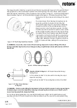
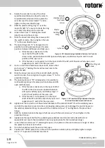
Carefully remove the plastic setting ring
“H” from the main SPI shaft “G”.
11.
Loosen the 2 screws
“
I
”
holding the cam disc to the shaft and lift the cam disc over the heads of these
screws.
M4 x 8
stainless steel
screw
M6 x 30
stainless steel
captive screw
M2.5 x 5
stainless steel
screw
D
ve
E
–
F
–
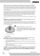
Figure 5
–
SPI Commissioning: Access
G
–

