Page 7 of 12
SPI
www.rotork.com
PUB132-002-00_0219
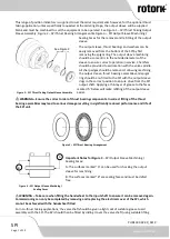
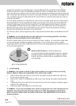
This range of position indicators is supplied to suit the order requirements however, for the optional thrust
taking application, unless specifically requested at the ordering stage, the output sleeve will be supplied
blank and must be machined to suit the equipment to be operated. See Figure 1
–
SPI Thrust Taking Output
Sleeve Assembly, Figure 2
–
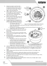
SPI Thrust Bearing Arrangement & Figure 3
–
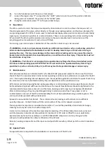
SPI Output Sleeve Machining /
Sealing Faces for the removal and re-fitting of the output
sleeve.
The output sleeve, thrust bearings and washers can be
easily removed from the bottom of the SPI by first
removing the spigot ring. The output sleeve machining
should be concentric to the outside diameters of the
sleeve to ensure correct operation in service. Chamfers
should be provided to aid location with the valve spindle.
All sharp edges should be removed. Following machining,
the output sleeve, thrust bearing assemblies and spigot
ring should be re-fitted to the SPI with the output sleeve
dogs in the correct position to ensure drive from the SPI
output shaft. Applying a thin layer of grease to the faces
marked ‘A’
below will make refitting of the output sleeve
easier.
⚠
WARNING
–
Ensure the correct order of thrust bearing components. Incorrect fitting of the thrust
bearing assemblies may lead to serious damage resulting in significantly reduced performance and life of
the SPI unit.
Important Notes for Figure 3
A: The surfaces marked
“
A
”
can be used for chucking the output
sleeve for machining.
B: The surfaces marked
“
B
”
are sealing faces and must be defect
free.
⚠
WARNING
–
Take care when fitting the handwheel to the input shaft to ensure it can be removed again.
Commissioning can only be completed by removing and replacing the electrical cover of the SPI, which
cannot be achieved with the handwheel fitted.
For non-thrust taking applications, the valve shaft should be given a light coat of suitable grease to aid
assembly with the SPI. The SPI should then be fitted by sliding it over the valve shaft (using suitable lifting
See Figure 2
–
SPI Thrust
Figure 1
–
SPI Thrust Taking Output Sleeve Assembly
A
ee
B
ng
Figure 3
–
SPI Output Sleeve Machining /
Sealing Faces
Figure 2
–
SPI Thrust Bearing Arrangement

