6
FA ROTEX Solaris DrainBack - 09/2016
3
x
Product description
3
Product description
3.1
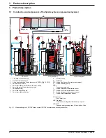
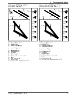
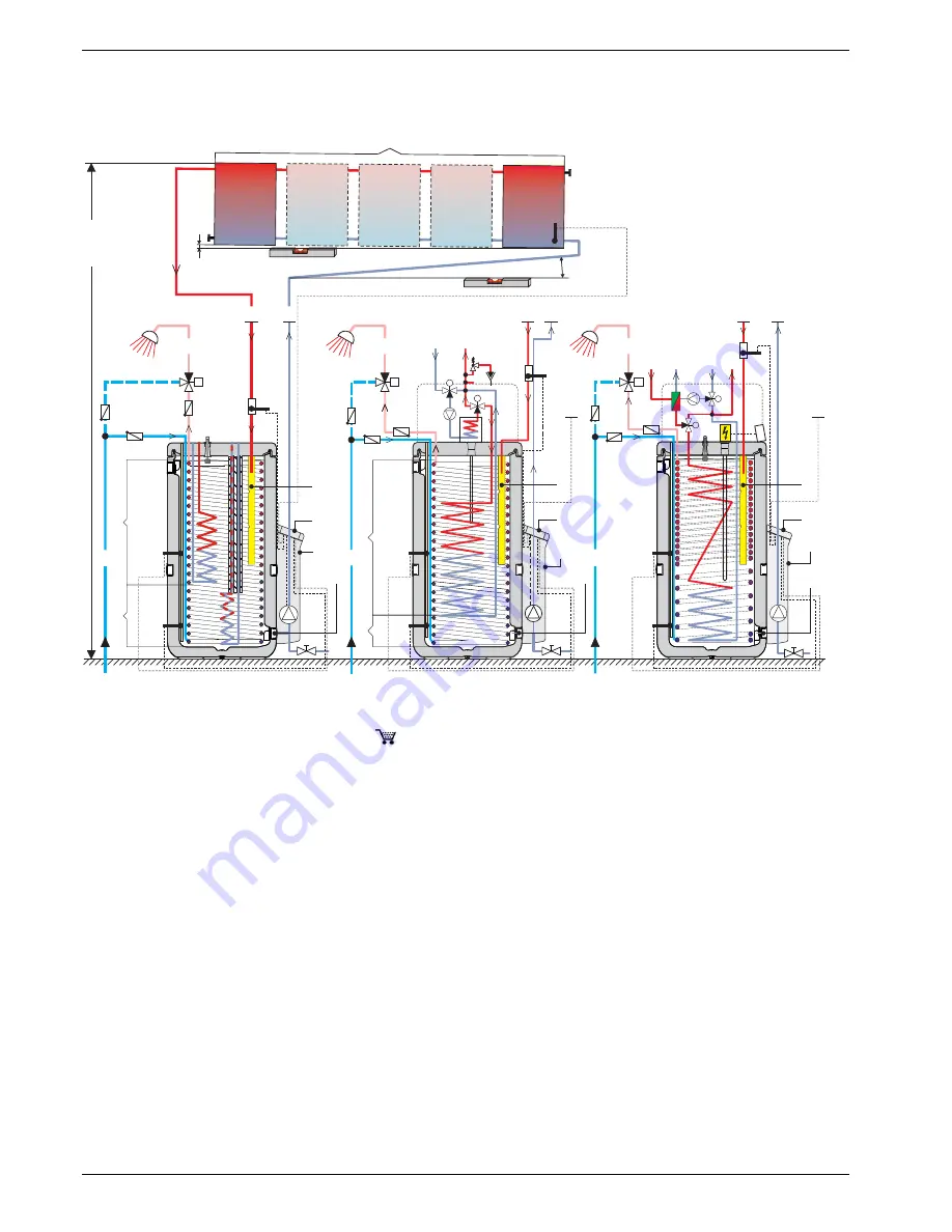
Construction and components of the Solaris system (unpressurised system)
1
Cold water connection pipe
2
Hot water distribution pipe
3
Filling and draining ball valve (accessory KFE BA,
16 52 15)
4
Solaris R4 control unit
5
Solar return flow pipe (bottom on the solar panel)
6
Solar inflow pipe (top on the solar panel)
7
Solar panel array
8
Solar inflow layering pipe
9
Solar return flow connection
A
Hot water zone
B
Solar zone
FLS Solaris FlowSensor (flow rate measurement)
P
S
Solaris operating pump
RPS4
Control and pump unit
T
K
Solaris solar panel temperature sensor
T
R
Solaris return flow temperature sensor
T
S
Solaris storage tank temperature sensor
T
V
Solaris inflow temperature sensor
GCU compact
Gas Combi Unit
HPSU compact
Solar tank with integrated interior heat pump unit
SCS/HYC
Sanicube energy storage tank Solaris / HybridCube
Fig. 3-1
Standard design of a ROTEX Solaris system (ROTEX recommends a two-way connection)
M
A
B
AB
M
B
A
AB
P
S
SCS/HYC
≤12 m
4
4
4
8
9
9
9
FLS
T
V
A
B
1
2
2
2
T
K
T
K
T
K
>2%
≥0,5 %
6
6
6
7
5
5
5
T
S
T
R
1
GCU compact
HPSU compact
T
V
P
S
A
B
T
S
T
R
1
3
3
3
8
8
FLS
FLS
P
S
T
S
T
R
T
V
RPS4
RPS4
RPS4
M
A
B
M
A
B


