background image

16

NOTE

:

 When using digital connections, you

should also make the analog audio input con-
nections described previously. The analog
connection is necessary to record to an ana-
log recorder in some circumstances or for
ZONE 2 operation

Digital Outputs 


The RSP-1098 has four digital outputs (two
coaxial and two optical) to send the digital
signal from any of the digital inputs to a digi-
tal recorder or outboard digital processor.
When a digital input source signal is selected
for listening, that signal is automatically sent
to both digital outputs for recording.

NOTE

Only digital signals from source com-

ponents are available at these outputs. Ana-
log signals cannot be converted and are not
available at the digital outputs.

Other Connections

AC Input 

Your RSP-1098 is configured at the factory for
the proper AC line voltage in the country where
you purchased it (USA: 115 volts/60Hz AC
or CE: 230 volts /50 Hz AC ). The AC line
configuration is noted on a decal on the back
of your unit.

Plug the supplied cord into the AC INPUT
receptacle on the back of the unit.

NOTE

Memorized settings and video labels

are preserved indefinitely, even if the
RSP-1098 is disconnected from AC power.

Master Power Switch 

The large rocker switch on the rear panel is a
master power switch. When it is in the OFF
position, power to the unit is completely off.
When it is in the ON position, the front panel
STANDBY and remote control ON/OFF but-
tons can be used to active the unit or put it
standby mode.

NOTE

After all connections are completed,

the rear panel master power switch should
be put in the ON position and usually left in
that position.

12V TRIGGER Connections 

Many Rotel amplifiers offer the option of turning
them on and off using a 12 volt trigger. These
four connections provide this 12 volt trigger
signal from the RSP-1098. When the RSP-1098
is activated, a 12 volt DC signal is sent to the
amplifiers to turn them on. When the RSP-1098
is put in STANDBY mode, the trigger signal is
interrupted and the amplifiers turn off.

To use the remote turn on feature, connect one
of the RSP-1098’s 12V TRIG OUT jacks to the
12 volt trigger input of a Rotel amplifier, us-
ing a cable with mono 3.5 mm mini-plugs on
both ends. The +12 V DC signal appears at
the “tip” connector.

NOTE

The 12V Trigger outputs can be config-

ured to turn on only when specific input
sources are activated. See the Input Setup
and Zone 2 Setup menus in the Setup section
of this manual for details.

REM IN Jacks 

Three 3.5 mm mini-jacks (labeled REM IN,
ZONE 2, and ZONE 3) receive command
codes from an industry-standard infrared re-
ceivers (Xantech, etc.), used when the IR sig-
nals from a hand held remote control cannot
reach the front panel IR sensor.

EXT:

 The EXT jack is used with an outboard

IR receiver to duplicate the front panel IR sen-
sor. This feature is useful when the unit is in-
stalled in a cabinet and the front panel sen-
sor is blocked or when IR signals need to be
relayed to other components.

ZONE 2 and ZONE 3: 

These two jacks are

used with IR repeater systems to receiver sig-
nals from IR control systems in remote loca-
tions. For example, remote control signals sent
to the ZONE 2 REM IN control the ZONE 2
features of the RSP-1098 and can be relayed
to other components. Remote control signals
sent to the ZONE 3 REM IN can be used to
select the RECORDING source (the signal
available at the TAPE OUT connections).

Consult your authorized Rotel dealer for in-
formation on external receivers and the proper
wiring of a 3.5 mm mini-plugs to fit the REM
IN jacks.

NOTE

The IR signals from the EXT REMOTE

IN jack (as well as those from the ZONE 2/
ZONE 3 REMOTE IN jacks) can be relayed
to source components using external IR emit-
ters or hard-wired connections from the IR
OUT jacks. See the following section for ad-
ditional information.

IR OUT Jacks 

The IR OUT 1 & 2 jacks send IR signals re-
ceived at the ZONE REM IN jacks or the EXT
REM IN jack to an infrared blaster or emitter
placed in front of a source component’s IR
sensor. In addition, the IR OUT can be hard-
wired to Rotel CD players, DVD players, or
tuners with a compatible connector.

These outputs are used to allow IR signals from
Zone 2 to be sent to the source components,
or to pass along IR signals from a remote in
the main room when the sensors on the source
components are blocked by installation in a
cabinet.

See your authorized Rotel dealer for information
on IR emitters and repeater systems.

Computer I/O 

The RSP-1098 can be operated from a com-
puter with audio system control software from
third-party developers. This control is accom-
plished by sending operating codes from the
computer via a hard-wired RS-232 serial con-
nection. In addition, the RSP-1098 can be up-
dated using special software from Rotel.

The COMPUTER I/O input provides the nec-
essary network connections on the rear panel.
It accepts standard RJ-45 8-pin modular plugs,
such as those commonly used in 10-BaseT UTP
Ethernet cabling.

For additional information on the connections,
cabling, software, and operating codes for com-
puter control or updating of the RSP-1098, con-
tact your authorized Rotel dealer.

Содержание RSP-1098

Страница 1: ...Owner s Manual RSP 1098 Surround Sound Processor SURROUND SOUND PROCESSOR RSP 1098 STANDBY ZONE 2 PATH SPEAKER PUSH MODE DISPLAY MENU MUTE FUNCTION VOLUME ...

Страница 2: ......

Страница 3: ...way Pay particular attention to the power cord at the plug and where it exits the back of the unit The power cord should be unplugged from the wall outlet if the unit is to be left unused for a long period of time Immediately stop using the component and have it inspected and or ser viced by a qualified service agency if The power supply cord or plug has been damaged Objects have fallen or liquid ...

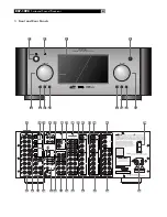
Страница 4: ...RSP 1098 POWER CONSUMPTION 70 WATTS ON OFF POWER S VIDEO COMPOSITE 3 ZONE2 1 2 SURROUND SOUND PROCESSOR RSP 1098 STANDBY ZONE 2 PATH SPEAKER PUSH MODE DISPLAY MENU MUTE FUNCTION VOLUME 4 3 1 2 5 12 6 7 8 9 10 11 13 14 15 20 16 17 40 26 18 27 29 28 30 32 19 22 21 24 25 23 34 33 31 35 38 37 36 39 ...

Страница 5: ... 3 4 5 6 7 8 9 10 0 X M MUTE DISC 2 DISC 1 CD DVD DISC 3 DISC 4 DISC 5 PROG RANDOM REPEAT DISC DISC DISPLAY AUDIO ANGLE SBTITLE ZOOM RESUME REPEAT A B GOTO SLOW INPUT 1 INPUT 2 INPUT 3 TV VCR RECORD CH VOL ON OFF FRQ DIRECT TUNE PRESET BAND FM MONO GUIDE MENU OSD CTR SUR SUB SEARCH SEARCH WAITING LEARN EDIT REPT CLONE LOADING RECEIVER TRANSMITTER WAITING LEARN EDIT REPT CLONE LOADING RECEIVER TRAN...

Страница 6: ...Front CROSSOVER 100Hz DOLBY Small DTS Small STEREO MPEG Large MUSIC Small SPEAKER SETUP MENU INPUT SETUP LISTEN CD VID INPUT Video 1 INPUT LABEL _______ INPUT Coaxial 2 CINEMA EQ Off 12V TRIGGER 1 DEFAULT MODE Dolby 3 Stereo GROUP DELAY 200ms MAIN MENU INPUT SETUP LISTEN Multi Input VID INPUT Video 1 INPUT LABEL _______ 12V TRIGGER 1 LFE REDIRECT On MAIN MENU INPUT SETUP LISTEN CD VID INPUT Video ...

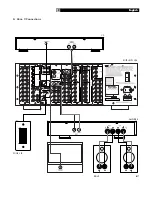
Страница 7: ...7 4 Outputs SURROUND SOUND PROCESSOR MODEL NO RSP 1098 POWER CONSUMPTION 70 WATTS ON OFF POWER S VIDEO COMPOSITE 3 ZONE2 1 2 CENTER CENTER BACK SURROUND FRONT R L English TV SUBWOOFER RSP 1098 AMPLIFIER ...

Страница 8: ...R S VIDEO COMPOSITE 3 ZONE2 1 2 L R L R REC IN LINE OUT L R REC IN LINE OUT REC IN LINE OUT AUDIO S VIDEO COMPOSITE VIDEO ANALOG OUTPUT OPTICAL DIGITAL OUTPUT L R AUDIO OUTPUT DIGITAL OUTPUT S VIDEO COMPOSITE VIDEO OUTPUTS COMPONENT VIDEO Y CR CB VCR DVD RSP 1098 CD TAPE RSP 1098 Surround Sound Processor ...

Страница 9: ...9 SURROUND SOUND PROCESSOR MODEL NO RSP 1098 POWER CONSUMPTION 70 WATTS ON OFF POWER S VIDEO COMPOSITE 3 ZONE2 1 2 6 Zone 2 Connections ROTEL RSP 1098 CD AMPLIFIER ZONE 2 IR LEFT RIGHT English ...

Страница 10: ...5 VIDEO 1 3 Composite Video Outputs 15 VIDEO 1 5 S Video Inputs 15 VIDEO 1 3 S Video Outputs 15 VIDEO 1 4 Component Video Inputs 15 TV Monitor Outputs 15 ZONE 2 Video Outputs 15 Digital Audio Input Outputs 15 Digital Inputs 15 Digital Outputs 16 Other Connections 16 AC Input 16 Master Power Switch 16 12V TRIGGER Connections 16 REM IN Jacks 16 IR OUT Jacks 16 Computer I O 16 Making Connections 17 C...

Страница 11: ...omatic Surround Modes 24 Manually Selecting Surround Modes 24 Dolby Digital 5 1 Dolby Digital Surround EX 25 Dolby Digital 2 0 25 DTS 5 1 DTS 96 24 DTS ES 6 1 25 MPEG Multichannel 26 Digital Stereo PCM MP3 and HDCD 26 Analog Stereo 26 Other Settings 27 Temporary Speaker Level 27 Temporary Group Delay 27 Dynamic Range 27 Contour Tone Settings 27 Cinema EQ 28 Zone 2 Operation 28 Zone 2 Power On Off ...

Страница 12: ... for total compatibility Four DSP Music modes Other features Multi zone multi source capability with independent input selection and volume User friendly ON SCREEN DISPLAY OSD menu system with programmable labels for all inputs Choice of languages Learning remote control to operate the RSP 1098 and nine other components Upgradeable microprocessor software to accommodate future upgrades Four assign...

Страница 13: ...tions have been properly made Video cables should have a 75 ohm imped ance The S PDIF digital audio interface stan dard also specifies a 75 ohm impedance and all good digital cables adhere to this require ment Do NOT substitute conventional audio interconnect cables for digital or video signals Standard audio interconnects will pass these signals but their limited bandwidth reduce per formance Whe...

Страница 14: ...on the RSP 1098 to the left and right channel inputs of the amplifier powering the remote speakers using standard RCA audio cables Video Inputs Outputs These connections are used for connecting video signals to and from the RSP 1098 See the Making Connections section for specific instructions for each type of component The RSP 1098 provides Composite S Video and Component Video connections Composi...

Страница 15: ... OSD information displays such as vol ume setting etc are not displayed TV Monitor Outputs The TV MONITOR outputs of the RSP 1098 send the video signal to your TV monitor Three types of video output connections are provided RCA composite video S Video and Com ponent Video The composite video output only sends signals from composite video inputs to the TV moni tor The S Video output only sends sign...

Страница 16: ...REM IN Jacks Three 3 5 mm mini jacks labeled REM IN ZONE 2 and ZONE 3 receive command codes from an industry standard infrared re ceivers Xantech etc used when the IR sig nals from a hand held remote control cannot reach the front panel IR sensor EXT The EXT jack is used with an outboard IR receiver to duplicate the front panel IR sen sor This feature is useful when the unit is in stalled in a cab...

Страница 17: ...Video 4 inputs above assign the digital input to the VIDEO 4 input AM FM Tuner Connect the left and right analog outputs from the tuner to the AUDIO IN jacks labeled TUNER left and right There are no digital connections or video connections for an AM FM tuner Audio Tape Recorder Connect the left and right analog outputs from an audio tape deck to the AUDIO IN jacks labeled TAPE IN left and right C...

Страница 18: ...098 this section of the manual starts with explaining the basic layout and function of the front panel and the remote control Then we explain the basic operations such as turning the unit on and off adjusting volume select ing a source for listening etc Following that is a detailed explanation of surround sound modes and how to configure the RSP 1098 for various types of recordings Finally there a...

Страница 19: ...nts A separate manual gives detailed instructions on programming and using the RR 1050 to replace all of the remote controls in your sys tem The RR 1050 manual covers many extra features such as custom labeling of remote buttons that appear in its LCD display To avoid duplication we provide only basic informa tion about using the RR 1050 to operate the RSP 1098 in this manual Many of the RR 1050 f...

Страница 20: ...nnel stereo Pro Logic II Cinema Pro Logic II Music 5 channel ste reo or 7 channel stereo The function of these buttons varies depending on the type of re cording being played See the Manually Se lecting Surround Modes section for detailed information SUR Button This button is used in conjunction with the buttons for manual selection of surround modes and features See the Manually Selecting Sur rou...

Страница 21: ... can be independently selected for lis tening viewing in the main room for record ing or for listening viewing in a remote Zone 2 location The OSD and or TFT displays show the name of the current source selection as it is made The labels for all input sources can be custom ized to match your components All of the source inputs can be customized using the OSD configuration menus to accept either an...

Страница 22: ... front right center and surround chan nels A music mode makes Pro Logic II an excellent choice for audio CDs Dolby Digital In 1992 an digital recording system called Dolby Digital was first used in the film indus try Dolby Digital is a recording playback sys tem that uses compression techniques to store large amounts of audio data efficiently much like the JPEG format stores large photographs in s...

Страница 23: ...tomatic with one exception Some Surround EX titles do not have the detection flag encoded on the disc To activate the Dolby Digital Surround EX features for these discs or for standard 5 1 channel Dolby Digital discs you must manu ally activate Dolby Surround EX processing The RSP 1098 also features Rotel XS eXtra Surround processing that automatically ensures optimum extended surround performance...

Страница 24: ...matic with detection triggered by a flag embedded in the digital recording telling the RSP 1098 what decoding format is required For example when Dolby Digital 5 1 or DTS 5 1 channel surround is detected the RSP 1098 activates the proper decoding The unit will also detect DTS ES Matrix 6 1 or DTS ES Discrete 6 1 discs and activate DTS ES Extended Surround decoding Dolby Digital Surround EX recordi...

Страница 25: ...same options You should force Surround EX on for non flagged discs that are labeled Dolby Digital Surround EX Rotel XS processing of standard 5 1 channel discs will provide a more diffuse surround effect than the more highly localized Dolby EX decoding and will probably be the best 6 1 channel option for non Surround EX discs On a 6 1 7 1 system with a Dolby Digital Surround EX disc Press the SUR ...

Страница 26: ... Emu lation option in Pro Logic II mode Press the buttons on the remote to toggle select the desired option On the front panel press the MODE button twice while in Pro Logic II mode Then rotate the FUNCTION knob to select the option Select the Cinema or Music option in Neo 6 mode Press the buttons on the remote to toggle select the desired option On the front panel press the MODE button twice whil...

Страница 27: ...nel 1 Press the SPEAKER button repeatedly un til you reach the GROUP DELAY option 2 Rotate the FUNCTION control to adjust the amount of delay applied to all channels Dynamic Range Dolby Digital recordings are capable of wide dynamic range the difference between the soft est and loudest sounds In some cases this may tax amplifiers and or speakers In other cases you may want to reduce the dynamic ra...

Страница 28: ...sing the rear panel POWER switch but ton the RSP 1098 provides independent power on off operation for both zones Pressing the remote control ON OFF buttons in the main room activates or deactivates the RSP 1098 in the main room only and has no effect on Zone 2 Conversely activating or deactivat ing Zone 2 has no effect on the main listen ing room However placing the rear panel master POWER switch ...

Страница 29: ...reen which has links to all other menus If a menu is already vis ible push this button to cancel the display The MENU button on the front panel provides the same function DOWN UP Buttons Press to move up and down in the lists of menu items that ap pear on the OSD screens Buttons Press to change the cur rent settings for a selected menu item on OSD screens ENTER Button From the SYSTEM STA TUS scree...

Страница 30: ...N CD VID INPUT Video 1 INPUT LABEL _______ INPUT Coaxial 2 CINEMA EQ Off 12V TRIGGER 1 DEFAULT MODE Dolby 3 Stereo GROUP DELAY 200ms MAIN MENU The INPUT SETUP menu configures the source inputs and is reached from the MAIN menu The screen provides the following options se lected by placing the highlight on the desired line using the UP DOWN buttons LISTEN changes the current listening input source ...

Страница 31: ...owing section for details GROUP DELAY Also known as lip sync delay this setting delays the audio signal for an input by the specified amount to match the video input This feature can be useful when the video signal is delayed more than the audio signal as sometimes happens with upconverted digital TV processors or when trying to match a radio broadcast with the video from a sports event The range ...

Страница 32: ...ER button DTS Neo 6 DTS Neo 6 MODE Cinema INPUT SETUP MENU When DTS Neo 6 is selected as the default surround mode on the INPUT SETUP menu there are additional option settings and pa rameters available to optimize the surround decoding for various types of recordings music or movie soundtracks DTS Neo 6 uses ma trix decoding algorithms to derive a center channel and surround channels from 2 chan n...

Страница 33: ...d generally not be the preferred configuration Speaker Setup SPEAKER SETUP FRONT Large CENTER Large SURROUND Large CENTER BACK Large1 SUBWOOFER Yes ADVANCED Enter MAIN MENU The SPEAKER SETUP menu is used to config ure the RSP 1098 for use with your specific loudspeakers and to determine the bass man agement configuration as described in the previous overview The menu is accessed from the MAIN menu...

Страница 34: ...wise the OFF setting for the subwoofer crossover is not avail able for SMALL speakers since SMALL means that the speaker will redirect its bass below a given crossover point to the subwoofer In addition the CROSSOVER setting is not avail able for the MULTI INPUT DOLBY large small none Sets the current speaker shown in the first line to LARGE SMALL or NONE overriding the master setting from the SPE...

Страница 35: ...he OSD menu system and select TEST TONE from the MAIN MENU to reach this screen When you enter the TEST TONE menu you will hear a test tone coming from the highlighted speaker Highlight different speakers by moving the cursor to the desired line using the UP DOWN buttons The test tone will shift accord ingly to the selected speaker Seated in the normal listening location shift the test tone to the...

Страница 36: ...ire system as a whole DEFEAT on off Selecting the ON setting defeats the contour adjustment bypassing the contour processing entirely for that speaker or group of speakers HF CONTOUR Adjusts the extreme high fre quency slope over a range of 6dB MIN to 6dB MAX Negative number settings reduce the high frequency output positive number settings increase it LF CONTOUR Adjusts the extreme low fre quency...

Страница 37: ...m performance when send ing a fixed level signal to a preamp or ampli fier with its own volume adjustment VOLUME In VARIABLE output mode this line shows the current volume setting for Zone 2 In FIXED output mode this volume setting es tablishes a permanent fixed output level for Zone 2 Move the highlight to the desired line using the UP DOWN buttons and use the but tons to adjust the volume level ...

Страница 38: ...o sound from digital sources Make sure that digital input connector is assigned to the proper source input and that the source input is configured to use the digital input rather than an analog input Check the configuration of the DVD player to ensure that the bitstream and or DTS digital output is activated No sound from some speakers Check all power amp and speaker con nections Check Speaker Con...

Страница 39: ...Hz 95 kHz 3 dB digital input Signal to Noise Ratio IHF A weighted 95 dB analog bypass 92 dB Dolby Digital dts 0dBFs Input Sensitivity Impedance Line Level 200 mV 100K ohms Preamp Output Level Output Impedance 1 0 V 250 ohms Contour LF HF 6 dB at 50 Hz 15 kHz Decodable Digital Input Signals Dolby Digital Dolby Digital EX DTS DTS ES DTS 96 24 LPCM up to 192K HDCD MP3 MPEG Multichannel Video Frequenc...

Страница 40: ...rd Street North Reading MA 01864 2699 USA Phone 1 978 664 3820 Fax 1 978 664 4109 Rotel Europe Dale Road Worthing West Sussex BN11 2BH England Phone 44 0 1903 221600 Fax 44 0 1903 221525 Rotel Deutschland Kleine Heide 12 D 33790 Halle Westf Germany Phone 49 05201 87170 Fax 49 05201 73370 www rotel com 082 OM RSP 1098 English 053103 ...

Отзывы: