


K
L
M
A
H
G
I
J
C
E
B
D
B
F
N
O
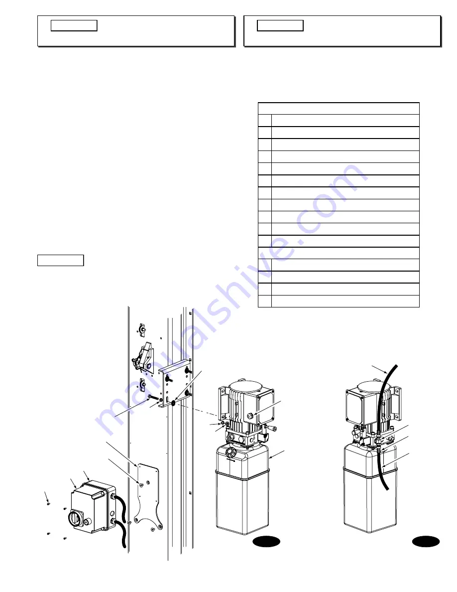
10. Power Unit for M Series Lifts:
A. Install (1) star washer onto one of the (4) 5/16"-18NC x 1-1/2”
Lg. HHCS.
This is very important for grounding.
Put the (4)
5/16"-18NC x 1-1/2" lg. HHCS through the holes in the power
unit bracket, using push nuts to hold in place, Fig. 10. With
motor being the heaviest part of the unit, two people lift the
unit, each with one hand supporting the motor. Position the
unit on the bolts with one person supporting the power unit
while the other installs 5/16” lock washers and 5/16”-18NC
Nuts.
B. Mount Adapter Plate on column, as shown in Fig. 10, using
(3) 5/16"-18NC x 1/2" Socket Flat Head Counter Sunk Machine
Screws.
C. Remove Control Panel Cover by loosening retaining screws
in each corner. Mount Control Panel Base on Adapter Plate,
as shown in Fig. 10, using (4) #8-32NC x 3/8" Socket Head Cap
Screws. Re-attach Control Panel Cover.
D. Install and hand tighten Branch Tee to pump until O-ring is
seated, Fig 11. Continue to tighten the lock nut to 14 - 20Nm
(1.4 - 2.1kg-m), or until the nut and washer bottom out against
the pump manifold.
NOTE:
You may still be able to rotate the
Branch Tee. This is acceptable unless there is seepage at
the O-ring. If so, slightly tighten the lock nut.
IMPORTANT
Over tightening lock nut may tear O-ring.
Fig. 11
Fig. 10
CAUTION
Installation of power unit for E series
lifts go to section 11.
CAUTION
Continue to section 13.
Fig. 10 Detail
A 5/16"-18NC x 1-1/2" Lg. HHCS
B 5/16" External Tooth Lock washer
C Push Nut
D 5/16"-18NC Hex Nut
E Strain Relief
F Power Unit
G Adapter Plate
H 5/16"-18NC x 1/2" Socket Flat Head MS
I Control Panel Base
J Control Panel Cover
K #8-32NC x 3/8" Hex SHCS
Fig. 11 Detail
L Overhead Hose
M Branch Tee
N Crimped Hose Sleeve (Typical)
O Power Unit Hose (Short)
7
Содержание SPO54E
Страница 2: ...Fig 1 Fig 2 A B C D E F G H I J A B C D E F G H I J 2...
Страница 31: ...NOTES...