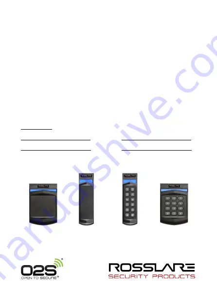
AY-G/H6xx0 Series
Open to Secure® (O2S®) Readers
Installation and User Manual
Models:
AY-G6270/G6280
AY-H6270/H6280
AY-G6370/G6380
AY-H6370/H6380
Страница 1: ...AY G H6xx0 Series Open to Secure O2S Readers Installation and User Manual Models AY G6270 G6280 AY H6270 H6280 AY G6370 G6380 AY H6370 H6380 AY H6270 H6280 AY G6270 G6280 AY G6370 G6380 AY H6370 H6380 ...
Страница 2: ...al property rights covering the subject matter in this manual TEXTS IMAGES AND ILLUSTRATIONS INCLUDING THEIR ARRANGEMENT IN THIS DOCUMENT ARE SUBJECT TO THE PROTECTION OF COPYRIGHT LAWS AND OTHER LEGAL RIGHTS WORLDWIDE THEIR USE REPRODUCTION AND TRANSMITTAL TO THIRD PARTIES WITHOUT EXPRESS WRITTEN PERMISSION MAY RESULT IN LEGAL PROCEEDINGS The furnishing of this manual to any party does not give t...
Страница 3: ...Instructions 14 6 1 Programming Menu 14 6 2 Entering Programming Mode 15 6 3 Exiting Programming Mode 15 6 4 Selecting Keypad Transmission Format 16 6 4 1 Keypad Transmission Formats 17 6 5 Changing the Programming Code 21 6 6 Changing the Facility Code 22 6 7 Setting the Backlight Behavior 22 6 8 Return to Factory Default Settings 23 6 9 Replacing a lost Programming Code 23 7 OSDP Operation 24 8 ...
Страница 4: ...Table of Contents iv AY G H6xx0 Series Installation and User Manual A 2 Rules for Wiegand 38 Bit 38A 30 B Declaration of Conformity 32 C Limited Warranty 33 ...
Страница 5: ...List of Figures AY G H6xx0 Series Installation and User Manual v List of Figures Figure 1 Mounting 9 ...
Страница 6: ...List of Tables vi AY G H6xx0 Series Installation and User Manual List of Tables Table 1 Wiring 10 Table 2 Reader Programming Menu 14 Table 3 Bit Description Table 27 ...
Страница 7: ...system with the maximum number of functions including future options Therefore not all functions described in this manual may be available in the specific system and or product configuration you purchased Incorrect operation or installation or failure of the user to effectively maintain the system relieves the manufacturer and seller from all or any responsibility for consequent noncompliance dama...
Страница 8: ...he CSN from MIFARE DESFire EV1 and MIFARE Classic EV1 credentials O2S ID data is stored in the secure memory of the MIFARE credential O2S ID data is AES 128 bit encrypted during transmission to the reader for MIFARE Plus and DESFire EV1 credentials 1 1 Box Content Before beginning verify that all of the following is in the box If anything is missing please report the discrepancy to your nearest Ro...
Страница 9: ...rill two holes sizes indicated on the template used for mounting the back plate onto the surface Figure 1 Figure 1 Mounting AY G6xx0 AY H6xx0 4 Insert a suitable wall plug into each screw hole 5 Drill a 10 mm 7 16 hole for the cable 6 Screw the back plate onto the wall 7 Connect the reader to the controller see Chapter 4 A linear type power supply is recommended 8 Attach the reader to the back pla...
Страница 10: ...ontroller cable by cutting its jacket back 3 2 cm 1 and strip the insulation from the wires 1 3 cm 3 Splice the reader s pigtail wires to the corresponding controller wires as indicated in Table 1 and cover each joint with insulating tape Table 1 Wiring Terminals Wire Color Output 1 Red VIN 6 16 VDC 2 Black Shield Ground 3 Green Data 0 Data 4 White Data 1 Clock 5 Purple Tamper Output 6 Orange Gree...
Страница 11: ...nd The reader s cable shield wire should be preferably attached to an earth ground or a signal ground connection at the panel or power supply end of the cable This configuration is best for shielding the reader cable from external interference To connect a terminal block reader to the controller 1 Prepare the controller cable by cutting its jacket back 5 cm 2 and strip the insulation from the wire...
Страница 12: ...dicate that the reader is working properly The LED returns to its Standby mode red for the AY x6x70 series and blue for the AY x6x80 series 2 Present the appropriate type of proximity card to the reader or enter a valid keypad entry The reader emits a beep 0 5 seconds The LED changes momentarily to green and then returns to its Standby mode red for the AY x6x70 series and blue for the AY x6x80 ser...
Страница 13: ... 4K AY H6x70 and AY G6x70 MIFARE Plus X 2K 4K MIFARE Plus S 2K 4K MIFARE Classic EV1 1K 4K 5 2 Wiegand Output For O2S credentials the reader outputs the ID data stored in the secure memory sector file of the credential The ID data defines the output as Wiegand and also determines the bit length of the output For example when reading an O2S 26A format credential the reader outputs a Wiegand 26 Bit ...
Страница 14: ...s are marked by Table 2 Reader Programming Menu Menu Description Default 1 Selecting Keypad Transmission Format 1 Single Key Wiegand 6 Bit Rosslare Format 2 Single Key Wiegand 6 Bit with Nibble Parity Bits 3 Single Key Wiegand 8 Bit Nibbles Complemented 4 4 Keys Binary Facility code Wiegand 26 Bit 5 1 to 5 Keys Facility code Wiegand 26 Bit 6 6 Keys Binary Coded Decimal BCD and Parity Bits Wiegand ...
Страница 15: ...and the unit returns to Standby mode To enter Programming mode 1 Press four times The yellow LED blinks 2 Enter your Programming code If the Programming code is valid and the unit is in Programming mode and the yellow LED is lit 6 3 Exiting Programming Mode To exit Programming mode 1 Press You hear a buzzing beep This indicates that the unit has returned to Standby mode Wrong entries may reset the...
Страница 16: ...h Nibble Parity Bits 3 Single Key Wiegand 8 Bit Nibbles Complemented 4 4 Keys Binary Facility Code Wiegand 26 Bit 5 1 to 5 Keys Facility Code Wiegand 26 Bit 6 6 Keys BCD and Parity Bits Wiegand 26 Bit 8 1 to 8 Keys BCD Clock Data Single Key 9 Single Key Wiegand 4 Bit When selecting Option 8 the right LED turns orange and an additional input is required to specify the number of keys in the PIN code...
Страница 17: ...Bit Nibble and Parities Each key press immediately sends 4 bits with 2 parity bits added even parity for the first 3 bits and odd parity for the last 3 bits 0 0 0000 1 6 1 0110 0 1 0 0001 0 7 1 0111 1 2 0 0010 0 8 1 1000 1 3 0 0011 1 9 1 1001 0 4 1 0100 1 1 1010 0 A in Hexadecimal 5 1 0101 0 1 1011 1 B in Hexadecimal Option 3 Single Key Wiegand 8 Bit Nibbles Complemented This option inverts the mo...
Страница 18: ... generates a beep and is ready to receive a new 4 digit keypad PIN code If the entry of the 4 digit keypad PIN code is disrupted and no number key is pressed within 5 seconds the keypad clears the PIN code entry buffer generates a beep and is ready to receive a new 4 digit keypad PIN code EP FFFF FFFF AAAA AAAA AAAA AAAA OP Where EP Even parity for first 12 bits OP Odd parity for last 12 bits F 8 ...
Страница 19: ... buffer generates a medium length beep and is ready to receive a new 1 to 5 digit keypad PIN code EP FFFF FFFF AAAA AAAA AAAA AAAA OP Where EP Even parity for first 12 bits OP Odd parity for last 12 bits F 8 Bit Facility code A 16 Bit code generated from keyboard Option 6 6 Keys BCD and Parity Bits Wiegand 26 Bit This option sends buffer of 6 keys adds parity and sends a 26 bit BCD message Each ke...
Страница 20: ...out a Facility code like standard Clock and Data card output The keypad PIN code can be one to eight digits in length The PIN code length is selected while programming the reader for Option 8 The reader transmits the data when it receives the last key press of the PIN code The data is sent across the two data output lines as binary data in Clock Data format If or is pressed during PIN code entry t...
Страница 21: ...mal 5 0101 1011 B in Hexadecimal 6 5 Changing the Programming Code The Programming code cannot be erased the code 0000 is invalid and does not erase the Programming code The factory default 4 digit Programming code is 1234 To change the Programming code 1 Enter Programming mode 2 Press 3 to enter Menu 3 The green LED blinks 3 Enter the new 4 digit code you wish to set as the Programming code The L...
Страница 22: ...hree beeps The system returns to Standby mode 6 7 Setting the Backlight Behavior To set the backlight behavior 1 Enter Programming mode 2 Press 6 to enter Menu 6 The green LED blinks 3 Enter one of the following codes 0 Always off 1 Always on 2 Backlight is off activates for 10 seconds when a key is pressed Mode LED also goes on after which it dims until off Mode LED also goes off 3 Backlight is d...
Страница 23: ...memory is erased you hear three beeps and the controller returns to Standby mode If the Programming code is invalid you hear a long beep and the controller returns to Standby mode without erasing the memory of the controller 6 9 Replacing a lost Programming Code In the event that the Programming code is forgotten the unit may be reprogrammed in the field using the following instructions 1 Remove p...
Страница 24: ...and On OSDP DIP Switch 2 This switch is used to determine what cards are read Off O2S cards and CSN of non O2S cards On O2S only DIP Switch 3 This switch is reserved for future use DIP Switches 4 to 8 These switches set the address of the reader for OSDP protocol DIP Switch 4 is MSB and DIP Switch 8 is LSB The address is the DIP switch state 1 Examples All the DIP switches in Off position state is...
Страница 25: ...ol Input 1 Green LED control TTL LED Control Input 2 Red LED control TTL Auxiliary Input Buzzer control TTL Auxiliary Output Tamper output open collector active low max sink current 30 mA Maximum Cable Distance to Controller Wiegand 150 m 500 ft with 18 AWG cable OSDP RS 485 1200 m 4 000 ft with 2x2 18 AWG twisted shielded cable Environmental Characteristics Operating Temp Range 31 C to 63 C 24 F ...
Страница 26: ...5 3 x 42 0 x 31 0 mm 5 7 x 1 7 x 1 2 in AY H6xx0 120 0 x 80 0 x 31 0 mm 4 7 x 3 2 x 1 2 in Weight of Pigtail Models AY G6270 155 g 5 5 oz AY G6280 153 g 5 4 oz AY G6370 236 g 8 3 oz AY G6380 231 g 8 1 oz AY H6270 161 g 5 7 oz AY H6280 168 g 5 9 oz AY H6370 220 g 7 8 oz AY H6380 218 g 7 7 oz Weight of Terminal Block and OSDP Models AY G6270 144 g 5 1 oz AY G6280 135 g 4 8 oz AY G6370 218 g 7 7 oz A...
Страница 27: ... on the card The readers support any O2S card from 26 bit to 128 bit For more details on supported formats and custom formats contact your Rosslare Sales representative The following subsections show examples for two of the supported O2S formats Wiegand 26 Bit 26A Wiegand 38 Bit 38A Table 3 is a key to the tables appearing in the subsections below Table 3 Bit Description Table D Card Number F Faci...
Страница 28: ...iegand 26 Bit 26A Field ID Data Facility Code Parity Bits of Bits 16 8 2 Range 65 535 255 N A Wiegand 26 Bit Reader Output Bit 1 E Even parity of bits 2 to 13 designated by X Bit 26 O Odd parity of bits 14 to 25 designated by X Bit 2 to 9 F 8 Bit Facility Code Bit 10 to 25 D 16 Bit ID Data ...
Страница 29: ...Wiegand Output Formats AY G H6xx0 Series Installation and User Manual 29 Example FC 59 ID 21 003 ...
Страница 30: ...5 535 1 023 127 3 N A Wiegand 38 Bit Rosslare Proprietary Reader Output Bit 2 O Odd parity of bits 3 to 20 designated by Parity Mask X Bit 1 E Even parity of bits 2 to 38 designated by Parity Mask X Bit 5 to 14 F 10 Bit Facility Code Bit 15 to 21 S 7 Bit Site Code Bit 22 to 37 D 16 Bit ID Data Bit 38 E Even parity of bits 20 to 37 designated by Parity Mask X Bit 3 to 4 I 3 Bit Card Issue Number ...
Страница 31: ...Wiegand Output Formats AY G H6xx0 Series Installation and User Manual 31 Example ISSUE No 0 FC 905 Site Code 103 ID 9 029 ...
Страница 32: ... reasonable protection against harmful interference in a residential installation This equipment generates uses and can radiate radio frequency energy and if not installed and used in accordance with the instructions may cause harmful interference to radio communications However there is no guarantee that interference will not occur in a particular installation If this equipment does cause harmful...
Страница 33: ...3 C Limited Warranty The full ROSSLARE Limited Warranty Statement is available in the Quick Links section on the ROSSLARE website at www rosslaresecurity com Rosslare considers any use of this product as agreement to the Warranty Terms even if you do not review them ...
Страница 34: ...05 0069 support na rosslaresecurity com Europe Rosslare Israel Ltd Rosh HaAyin Israel Tel 972 3 938 6838 Fax 972 3 938 6830 support eu rosslaresecurity com Latin America Rosslare Latin America Buenos Aires Argentina support la rosslaresecurity com China Rosslare Electronics Shenzhen Ltd Shenzhen China Tel 86 755 8610 6842 Fax 86 755 8610 6101 support cn rosslaresecurity com India Rosslare Electron...