


HDBH Series Operating Instructions
www.rosscontrols.com
5
7.1.2. Filtration:
Fluid cleanliness is a necessity in any hydraulic system. Fluid
filters need to be installed and maintained in the system to provide the required level of
cleanliness. Filters can be placed in the inlets.
7.1.3. Accessory Ratings:
All accessories used in combination with the
selected or intended HDBH valve system must be used in accordance with the HDBH
specifications.
7.2. Electrical Connections
Install the electrical connectors (EN 175301-803 Form A type, pre-wired or non-
prewired) for both the valve solenoids.
Install the inductive position switch connector (M12, 5-pin, A-coded) on each valve and
follow the electrical wiring schematics of the switch on page 2.
8. Commissioning and Operation
CAUTIONS
Damage to health due to loud noise!
Levels above 70 dB(A) may lead to damage to health!
f
Always wear ear protectors when working on the product.
Before commissioning, the installation must be carefully inspected by a qualified,
trained professional.
Make sure that the technical specifications match the operating criteria of the machine
and/or the hydraulic system.
8.1. HDBH Test Procedure for Valve Operation
NOTE 1: This valve test procedure only checks for proper function of the HDBH
system. Please refer to the HDBH Integration Guide for the External Monitoring
Validation Procedure.
NOTE 2: The valve test procedure requires fault simulation. It will be necessary
to induce faults electrically by disabling a different solenoid or switch at different
times. This will be most easily done by disconnecting solenoid or switch cables
at the valve.
NOTE 3: The HDBH is designed to work in association with a directional control
valve and a cylinder (or other actuator). The following test procedure only
checks the function of the HDBH system, and it may be necessary to modify this
procedure to accommodate the various operating modes of the directional valve
being used with the HDBH.
NOTE 4: The PNP position switches are supplied with both NC and NO contacts.
NOTE 5: - indicates no change from previous step.
Step
Action
Sol 1A Sol 1B
Flow
YES/NO?
Switch Conditions
Pass/Fail
Switch 1A
Switch 1B
(NC)
(NO)
(NC)
(NO)
(P/F)
1
Energize
solenoid 1A ON
OFF
NO
OPEN CLOSED CLOSED OPEN
2
De-energize
both
solenoids
OFF
OFF
NO
CLOSED OPEN
-
-
3
Energize
solenoid 1B OFF
ON
NO
-
-
OPEN CLOSED
4
De-energize
both
solenoids
OFF
OFF
NO
-
-
CLOSED OPEN
5
Energize
both
solenoids
1A & 1B
ON
ON
YES
OPEN CLOSED OPEN CLOSED
6
De-energize
both
solenoids
OFF
OFF
NO
CLOSED OPEN CLOSED OPEN
8.1. Limitations Due to System Leakage
Even though the HDBH is designed to redundantly block flow, it is important to
periodically test for leakage within the HDBH and the system it controls, as any leak
within the HDBH itself, interconnecting hoses, connectors, cylinders or other actuators,
or even other valves in the circuit may cause unexpected movement. In order to test
for leakage within the HDBH itself, it is necessary to check for actuator (cylinder)
movement when the HDBH is in each of the following conditions:
WARNING
Performing this test could cause injury or damage to equipment due to unexpected or
uncontrolled movement. Take all necessary precautions to ensure worker safety prior to
initiating this test.
A) fully de-energized (both solenoids 1A & 1B de-energized)
B) solenoid 1A energized with solenoid 1B de-energized
C) solenoid 1A de-energized with solenoid 1B energized.
Depending on the application, it may be necessary to preposition actuators and/or
other valves such that energizing the HDBH would allow motion to occur. This sets up
the circuit so that the HDBH valve is the sole motion-controlling device during testing.
For example, if a cylinder is fully retracted, a leak that normally allows retract motion to
occur could be masked because the cylinder is already fully retracted.
This test helps to troubleshoot leaks within the HDBH system. Other leaks within the
associated system can affect the outcome of this test.
WARNING
If any leakage is discovered within the system, measures should be taken to eliminate the
leak(s) as failing to do so could limit the ability of the safety system to safely stop motion
when required.
WARNING
Continued operation of the system without periodic leakage inspections can lead to unexpected
movement.
9. Disconnecting and Removal
CAUTIONS
Risk of injury due to installation while pressurized or with live parts!
f
Disconnecting a hydraulic component while the system is pressurized or while electrical power
is supplied can result in injury or death due to sudden pressure release, unexpected movement,
or electric shock.
f
Isolate and lock out the electrical and hydraulic systems before disconnecting the unit
.
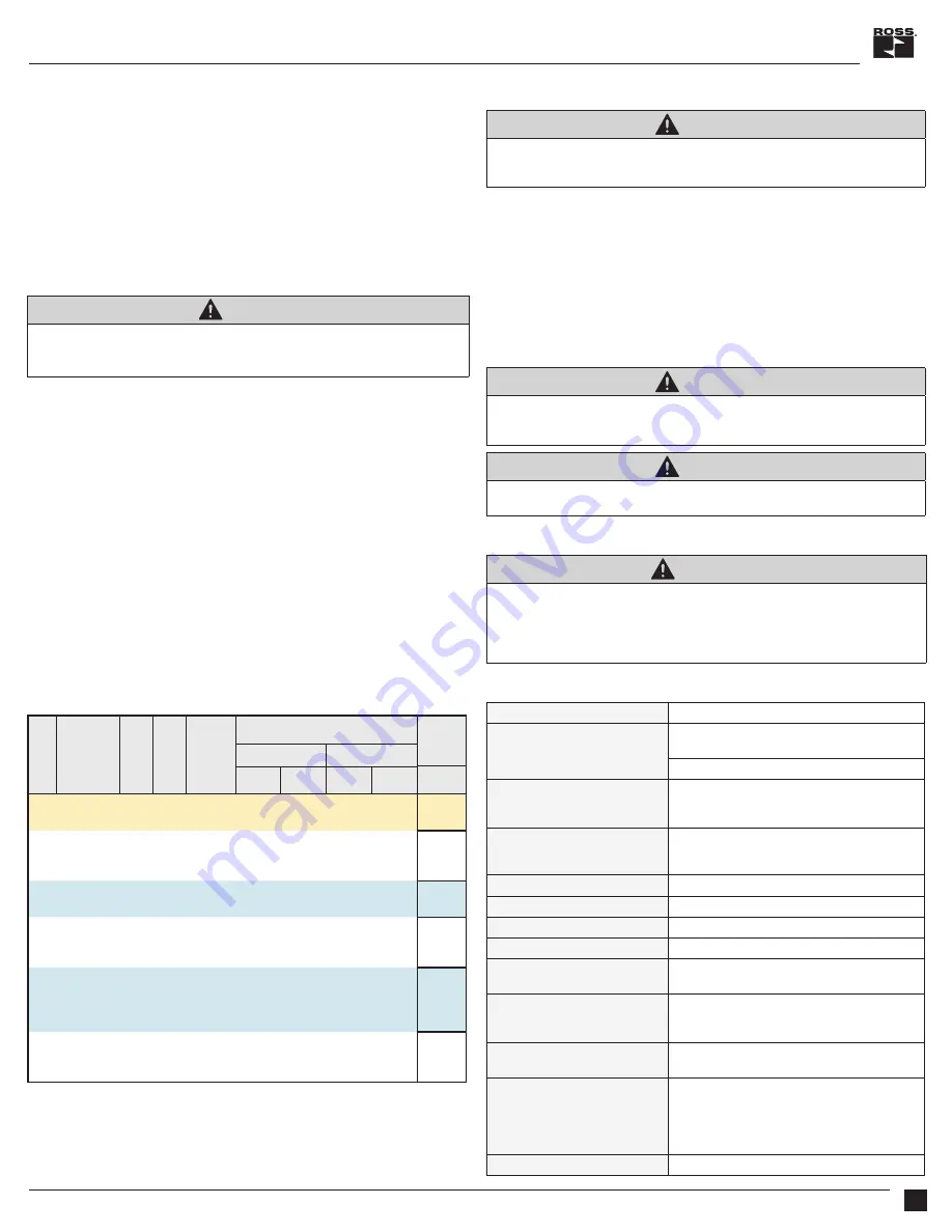
10. Technical Specifications
Construction Design
Spool type
Actuation
One solenoid per valve element
Solenoids must be operated synchronously
Direct solenoid operated, spring return
Mounting
Type:
Sandwich-style mounted (interposed) between
base/manifold and directional valve
Footprint:
ISO 4401-03-02-0-05 (NG 6 or D03)
Solenoids
Version as per VDE 0580. Rated for continuous duty.
Electrical connection according to EN 175301-803 Form A
Enclosure rating according to DIN 400 50 IP 65
Standard Voltages
24 volts DC
Power Consumption
(each solenoid)
30 watts
Inductive Position Switch
(2 per system)
PNP (M12, 5-pin, A-coded)
Maximum Current
(each switch)
400mA maximum
Temperature Range
(recommended)
Ambient: -
22° to 160°F (-30° to 70°C)
Media:
-4° to 140°F (-20° to 60°C)
Flow Media
Hydraulic Fluids:
Mineral Oil HLP, HL-DIN 51524
Vegetable Oil HETG - VDMA 24568
Pressure
Ports P, A, B :
5000 psi (344 bar)
Port T :
3000 psi (210 bar)
Construction Material
Valve Body:
Cast Steel
Spool:
Steel
Seals:
Buna-N
End-brackets:
Unfilled Nylon 12
Side-brackets (label):
304 Stainless Steel
Functional Safety Data
MTTFd: 150 years