background image

20-02245   REV E 

1. 

Mount equipment as close as possible to the output shaft.  This minimizes 
bearing drag forces on the axis. 


2. 

Mount the equipment so that the center of gravity is close to the center of 
axis to minimize torque requirements.   In some cases it is advantageous 
to add counterweights to achieve a more balance configuration. 


3. 

When possible, minimize cross sectional area of the equipment that will be 
exposed to hydrodynamic drag forces. 


CONTROLLING THE UNIT 


Refer  to  the  communication  protocol  (21-30022)  for  controlling  your  pan-and-tilt.  
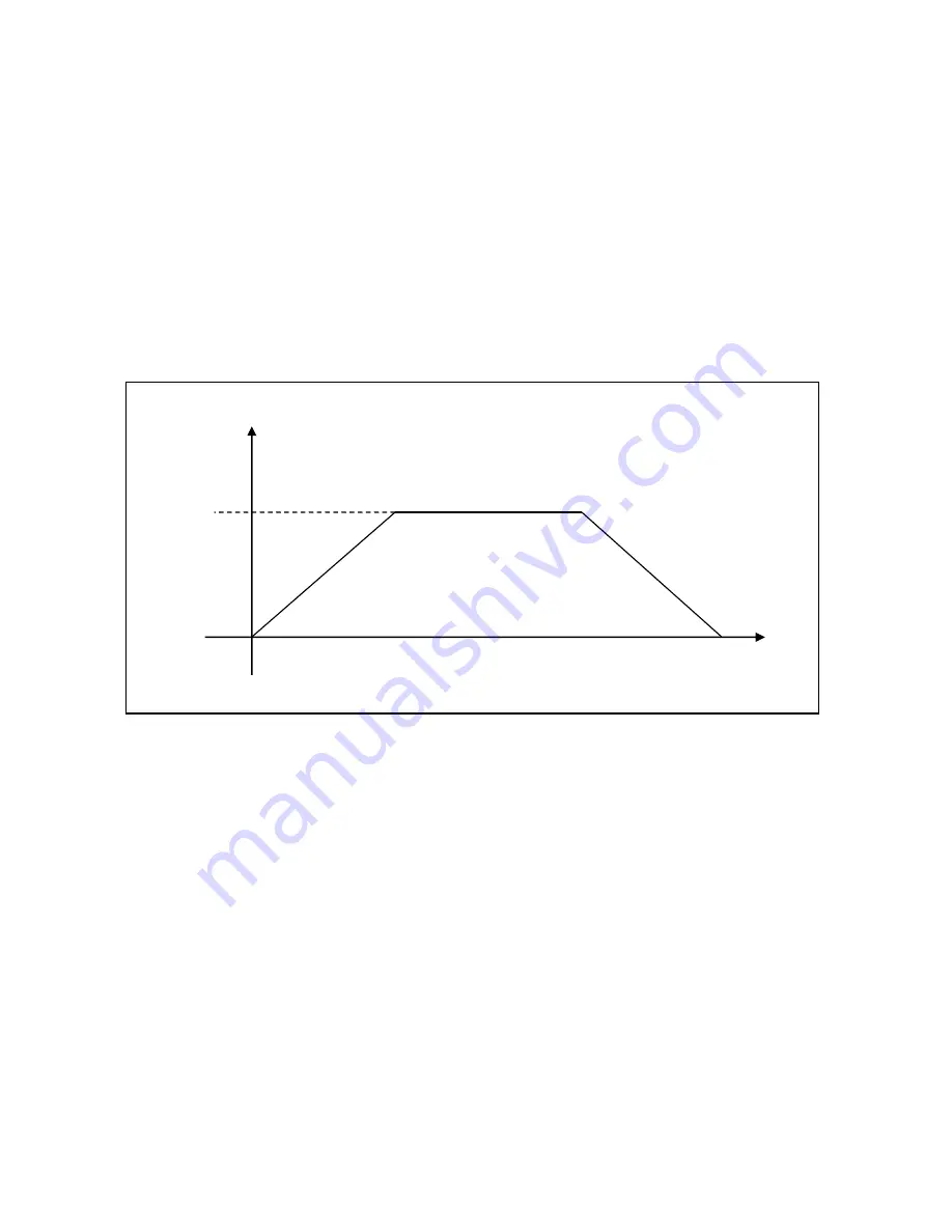
Movement  on  each  axis  will  follow  a  path  similar  to  the  figure  above  when  ramping 
commands  are  used.    The  user  can  send  rotate  or  position  commands  to  move  each 
axis.    To  operate  the pan-and-tilt  without  stalling  or  slipping,  the user  should  calculate 
the amount of torque required to hold the load on each axis.  Then, once this is known, 
the  user  should  refer  to  the  torque  curve  to  find  the  maximum  velocity  that  can  be 
achieved without a stall occurring.  For example, if the user knows their maximum load 
is  20  lbs.  at  a  foot  (requiring  20  ft-lbs.),  the  axis  should  not  move  faster  than  6.5 
degrees/sec.    The  user  should  not  send  rotate  commands  faster  than  6.5 
degrees/second  and  the  maximum  velocity  of  the  position  speed  profile  should  be 
adjusted  to  6.5  degrees/sec.    This  will  limit  the  maximum  velocity  on  position  moves 
only.  The axis will brake at the last commanded braking value.  Set the braking value 
according to the torque curve.  The user can also adjust the acceleration.   


BRAKING 

MAX  
VELOCITY 

VELOCITY 

DECEL = ACCEL 

ACCEL 

DISTANCE 

SPEED PROFILE 

Содержание PT-25FB-24VDC-RS-485

Страница 1: ...TER POSITIONERS MODEL PT 25FB 24VDC RS 485 MODEL R 25FB 24VDC RS 485 OPERATING AND MAINTENANCE MANUAL SERIAL NUMBER __________ SALES ORDER __________ 5618 Copley Drive San Diego CA 92111 7902 TEL 858...

Страница 2: ...cerbated over long cable lengths 3 LIST OF ROS UNDERWATER RS 485 PRODUCTS To satisfy customer needs ROS has developed turn key net workable underwater products Each of the products listed below has an...

Страница 3: ...pplies can be the source of electrical noise and may mislead the system designer or user to inappropriately attribute the noise to a device attached to the power conductors It is recommended to ensure...

Страница 4: ...ient because those devices are not as susceptible to electrical noise When a video camera is connected to the network and common power connections are made at the cable breakout hardware side instead...

Страница 5: ...V E V REVISION PAGE REV DESCRIPTION DATE INITIALS A Added Application Note page 8 16 06 SW B Added R 25FB 24VDC RS 485 12 12 06 RJL C SEE ECO 1251 07 14 08 GR D SEE EC 00605 02JUL10 BAL E SEE EC 01190...

Страница 6: ...is warranty shall be governed by the laws of the State of California In the event the defect is determined to be within the terms of this warranty then ROS agrees to repair and or replace at ROS s dis...

Страница 7: ...and are able to provide assistance during installation and or operation of these products If you have any questions or problems with this product that are not covered by this manual or instruction pl...

Страница 8: ...SPECIFICATIONS 3 CONNECTOR WIRING 5 INSTALLATION AND OPERATION 6 OPERATIONAL CHECK 6 INSTALLATION 6 EQUIPMENT MOUNTING 6 CONTROLLING THE UNIT 7 INTERCONNECTION 8 MAINTENANCE 9 FLUID VOLUME CHECK If eq...

Страница 9: ...oners are offered as air filled units for shallow applications or in air operation or as oil filled pressure compensated units suitable for deep water applications For problems or questions not covere...

Страница 10: ...to the shaft plate The circuit board receives the 24VDC nominal input voltage from an external remote Controller and generates the step sequence necessary to drive the stepper motor To operate the po...

Страница 11: ...0 5 to 10 0 1 degrees sec 0 083 to 1 66 RPM in 0 5 degree sec increments Torque 33 lbs ft 14 Nm minimum 5 degree sec Harmonic Gear Backlash 36 arc minutes 0 6 degrees Network Ability Up to 32 ROS RS...

Страница 12: ...rque versus Rotation Speed 0 10 20 30 40 50 60 70 0 5 1 1 5 2 2 5 3 3 5 4 4 5 5 5 5 6 6 5 7 7 5 8 8 5 9 9 5 10 Rotation Speed degrees second Torque lb ft PT 25 with 160 1 gears Current Draw versus Rot...

Страница 13: ...onnectors and wiring standards are available and details of these configurations are normally included in the manual Addendum CONNECTOR PIN CONNECTION FUNCTION 1 DC Common 2 24 VDC 3 RS 485 A 4 RS 485...

Страница 14: ...nstalled by mounting the positioner to a permanent structure Four 3 8 16 tapped holes are provided in the mounting boss for the rotator and pan and tilt Feedback units should be mounted to a MP 2 moun...

Страница 15: ...to move each axis To operate the pan and tilt without stalling or slipping the user should calculate the amount of torque required to hold the load on each axis Then once this is known the user should...

Страница 16: ...the mating connector lightly with silicone spray and push together The other end of the cable attaches to a controller which provides the required power to the connector pins as well as control signal...

Страница 17: ...ofram end of the housing A protective cover with holes for water flow covers the Bellofram When the fluid volume is normal the Bellofram will expand outward Its position can be checked by visual obser...

Страница 18: ...all them in the grooves of the end cap Avoid excessive stretching of the O ring 5 Using silicone grease or O ring lubricant completely fill the top retaining ring groove If this is not done the sealin...

Страница 19: ...O ring sealing surfaces Keep these rings separate from the outer rings which retain the end cap The outer rings are made of stainless steel for corrosion protection If one of the retaining rings is w...

Страница 20: ...R FILLED With the end cap seal screws removed replace the end cap and slowly push it into the housing It may be necessary to rotate the output shaft slightly for proper gear engagement Install the ret...

Страница 21: ...ill leak Position the end cap assembly into the housing without pressing it in Since fluid may be ejected through the seal screws holes place a towel over the end cap to reduce the losses Push the end...

Страница 22: ...02247 Assy PT 25FB 24VDC RS 485 AIR SS 160 1 Gears 20 02216 Wiring Diagram PT 25FB 24VDC RS 485 20 10004 Installation Outline R 25DC FB AIR 20 10035 Assy R 25FB 24VDC RS 485 AIR AL 160 1 Gears 20 100...

Отзывы: