background image

9

Part 

3

3


Using the Operation Panel

When you install the rotary axis unit, the following keys operations and display menus are added. This section describes the added

functions. For information about the basic operation of the operation panel, refer to the manuals of the main unit.

3-1. Rotating the A Axis Using the Operation Panel

1

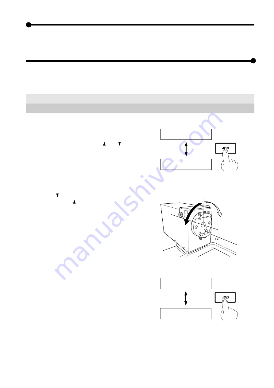
Hold down the [JOG] key for 0.5 seconds or longer. The

display changes to show the coordinates of the A axis.

When the power is switched on, the [   ] and [   ] keys on

the operation panel are assigned to Y-axis operation, and

the display also shows the Y-axis coordinates. Holding

down the [JOG] key for 0.5 seconds or longer switches

from the Y axis to the A axis.

2

Use the [   ] key to rotate in the positive direction (toward

the front) and the [   ] key to rotate in the negative direc-

tion (toward the back). Also, when you press the [JOG]

key to line up the [*] with [A], you can also use the dial to

perform these operations.

3

Holding down the [JOG] key again for 0.5 seconds or

longer changes from the A axis to the Y axis.

 X     0   *Y      0
 Z     0    --------

 X     0   *A      0
 Z     0    --------

Hold down for 0.5
seconds or longer

Negative direction

Positive direction

 X     0   *Y      0
 Z     0    --------

 X     0   *A      0
 Z     0    --------

Hold down for 0.5
seconds or longer

Содержание MODELA Pro ZCL-650

Страница 1: ...ts of this operation manual and the specifications of this product are subject to change without notice The operation manual and the product have been prepared and tested as much as possible If you find any misprint or error please inform us Roland DG Corp assumes no responsibility for any direct or indirect loss or damage which may occur through use of this product regardless of any failure to pe...

Страница 2: ......

Страница 3: ... the Z axis Direction 17 Differences in Height at the Seam Between the Front and Back Surfaces 17 5 2 How to Adjust the Center Z Offset 18 5 3 How to Adjust the Center Y Offset 20 Part 6 Cutting Using MODELA Player ver 3 22 6 1 Settings For the Rotary Axis Unit 23 6 2 The Tool Movement Range for MODELA Player ver 3 24 6 3 Getting Ready for Cutting 25 Method of Object Support 25 Cutting Parameters ...

Страница 4: ...gs that must be carried out The specific thing that must be done is indicated by the design contained within the circle The symbol at left means the power cord plug must be unplugged from the outlet Do not disassemble repair or modify Doing so may lead to fire or abnormal operation resulting in injury Do not use while in an abnormal state i e emitting smoke burning odor unusual noise or the like D...

Страница 5: ...r malfunction and ensure correct use Indicates a handy tip or advice regarding use In addition to the and symbols the symbols shown below are also used NOTICE Do not allow liquids metal objects or flammables inside the machine Such materials can cause fire ...

Страница 6: ...aces with ease When the rotary axis unit is installed you can carry out simultaneous three axis control for the X Y and Z axes or the X Z and A axes The A and Y axes do not operate simultaneously Simultaneous four axis operation of the X Y Z and A axes is not possible You can easily switch between the A and Y axes using commands or the operation panel The A axis has a positioning range of 0 to 1 0...

Страница 7: ...6 mm 1 3 mm 1 Rotary axis unit Cable clamp Screws 4 for securing the cable clamp and for the slider retainer Cap screws 4 for securing the rotary axis unit Y center detection pin diameter 6 mm Slider retainer Spacers 4 Washers 4 for securing the rotary axis unit ...

Страница 8: ... Part 2 Setting Up Tab Tab Slider Slider Attachment base Attachment base Set screws Workpiece retainer attachment Clamp marks Rotation axis center sensor Cable clamp Cable Workpiece mounting surface Drive side Support side ...

Страница 9: ...t to remove the six cap screws shown in the figure then detach the T slot table 4 Use two screws to attach the slider retainer to the side and temporarily secure the slider in place 5 Clean away any build up grime on the tabs and the sliders Place the rotary axis unit on the slider and secure in place using the four cap screws and washers while firmly press ing the tab against the slider If insuff...

Страница 10: ... of the rotary axis unit into the EXT 3 connector on the main unit Use a screwdriver to tighten the connector screws The machine will not operate if this cable becomes disconnected or loose Tighten securely 10 Store the center of rotation Y axis of the rotary axis unit in memory For information about how to do this refer to 3 3 Setting the Y and Z axis Origin Point at the A axis Center of Rotation...

Страница 11: ...he operation panel are assigned to Y axis operation and the display also shows the Y axis coordinates Holding down the JOG key for 0 5 seconds or longer switches from the Y axis to the A axis 2 Use the key to rotate in the positive direction toward the front and the key to rotate in the negative direc tion toward the back Also when you press the JOG key to line up the with A you can also use the d...

Страница 12: ...nd Z axis Origin Point at the A axis Center of Rotation Aligning the Y and Z axis origin point for workpiece coordinates with the A axis center of rotation makes it easy to determine coordi nates at times such as when performing multiple surface cutting The rotary axis unit offers as feature that makes it simple to perform this setting If you re using MODELA Player be sure to carry out these opera...

Страница 13: ... bell beeps when detection ends 8 Put back the sensor cover NOTICE Be sure to use the included Y center detection pin to perform this operation Using an end mill or the like may make accurate detection of the origin point impossible If Y axis center alignment of greater accuracy is required use the CENTER Y OFFSET function This makes it possible to correct for sensor error For detailed information...

Страница 14: ...the main menu 5 Turn the dial to line up the arrow with ROTARY CON TROL then press the ENTER key 6 Turn the dial to line up the arrow with Z CENTER MODE then press the ENTER key 7 Press the Z key to lower the tool until it touches the rotation axis center sensor As soon as the tool touches the sensor operation stops and the tool rises The center of rotation of the A axis is detected automatically ...

Страница 15: ...RESET Y POS 4 Y CENTER MODE 5 CENTER Y OFFSET 6 CENTER Z OFFSET 7 ROTARY USE TIME 8 To Main MENU 12 1 ROTATE 0deg EXIT 12 2 Z CENTER MODE Please Cursor Move 12 3 RESET Y POS Are You Sure ENTER 12 4 Y CENTER MODE Are You Sure ENTER 1000 to 1000 µm In step of 10 µm 1000 to 1000 µm In step of 10 µm 12 5 CENTER Y OFFSET 0 µm 12 6 CENTER Z OFFSET 0 µm 12 7 ROTARY USE TIME 0 hours 12 8 To Main MENU ENTE...

Страница 16: ...f the maximum cutting range This uses the rotational center sensor to set the Y axis origin point at a location where the tool center coincides with the A axis center Running this item initializes the CENTER Y OFFSET value to zero Stored in memory Yes Factory default 0 Setting range 1 000 to 1 000 µm Steps 10 This corrects coordinate misalignment of the Y axis origin point that Y CENTER MODE sets ...

Страница 17: ...wer than the range described above Amount of tool extension Interference between the rotary axis unit or workpiece retainer attachment and the tool or spindle unit Interference between the loaded workpiece and the tool or spindle unit Special care is needed when you attach square material as the workpiece because the corners may easily strike the tool when rotating the A axis 155 19 174 103 123 93...

Страница 18: ...rface of the workpiece retainer attachment 4 Tighten the set screws securely using even force If the workpiece is thin and the set screws do not reach insert the included spacer or the like and secure in place Take care not to apply excessive force when securing the workpiece in place Doing so may cause the workpiece to warp or deform during cutting When you are using a soft workpiece made of foam...

Страница 19: ... cutting as follows Inaccuracy in the Z axis Direction There is an error in the thickness of the object when cutting the front or back surface This is due to misalignment of the Z axis origin point Make correction as described in 5 2 How to Adjust the Center Z Offset Differences in Height at the Seam Between the Front and Back Surfaces There is an error in the depth of the object This results in d...

Страница 20: ... of Rotation 2 Load a box shaped workpiece then set theA axis origin point at a place where the surface is level Hold down the JOG key for 0 5 seconds or longer to return the and keys to Y axis opera tion For more information refer to 3 1 Rotating the A Axis Using the Operation Panel and 3 2 Setting theA axis Origin Point 3 Hold down the SPINDLE key for 0 5 seconds or longer to rotate the spindle ...

Страница 21: ...e and the actual measured value is the amount of error As a general guide the offset value should be one half of this Theoretical thickness coordinate a coordinate b Offset value theoretical thickness actual measured value 2 For example if coordinate a is 80 and coordinate b is 2 250 the theoretical thickness is 21 7 mm If the actual measured value is 21 8 mm the estimated offset value is 50 µm 9 ...

Страница 22: ... blade length at least one half of the thickness of the workpiece 2 Load a box shaped workpiece then set the A axis origin point at a place where the surface is level Hold down the JOG key for 0 5 seconds or longer to return the and keys to Y axis operation For more information refer to 3 1 Rotating the A Axis Using the Operation Panel and 3 2 Setting the A axis Origin Point 3 Hold down the SPINDL...

Страница 23: ...t between the two cuttings Whether the offset value should be positive or negative is determined by whether the upper cut surface the surface cut second is displace toward the front or the back of the machine Also as a general guide the offset value should be one half the amount of differ ence in heights When the upper side is displaced toward the front Positive offset value When the upper side is...

Страница 24: ...rface cutting These make it easy to perform two and four surface cutting This section describes the special features for the rotary axis unit Two surface Cutting Four surface Cutting 1st surface 0 degrees 3rd surface 90 degrees 2nd surface 180 degrees 4th surface 270 degrees 1st surface 0 degrees 2nd surface 180 degrees ...

Страница 25: ...on is added to the Set the maximum cutting depth screen This lets you specify the maximum cutting depth individually for the first through fourth surfaces The Finish selection specifying either Draft or Fine cutting becomes unavailable This is performed using the Set tings for Multiple surface Cutting wizard instead The Layout command on the Options menu becomes unavailable Specifying the cutting ...

Страница 26: ... Set the Dimension screen and the setting for maximum cutting depth see the figures below Refer to these when you are making sure there is no interference between the tool and the spindle For more information about how to make the setting for the cutting start location and the like refer to 6 5 Operation of MODELA Player ver 3 later in this part Part 6 Cutting Using MODELA Player ver 3 Tool Set th...

Страница 27: ...ameter and the cutting parameters for MODELA Player ver 3 Support length Tool diameter Path Spacing Fine Margin To display the values for Path Spacing and Fine Margin use MODELA Player ver 3 to make the sets for tool diameter and the workpiece then go to Options and click Custom Parameters Vertical walls remain as an outer border around the object When the cutting depth is considerable this become...

Страница 28: ...e tool diameter You also need to take into account the amount of overlap for a surface and the surface on the opposite side When you re using a square end mill zero overlap is theoretically acceptable but it results in a seam between the front and back It may be possible to reduce this by applying very slight overlap Also when you re using a ball end mill overlap greater than the tool diameter is ...

Страница 29: ...ming cutting from the third surface When there is absolutely no error in accuracy the cutting from the third surface should be perfectly flush with the first surface and inflict no damage on the finished surface In actual practice however eliminating error in accuracy completely is difficult There may be any number of possible causes including mechanical precision tool wobble the precision of the ...

Страница 30: ...the Four surface cutting offset value produces a correspondingly greater effect on the finished dimen sions About Four surface cutting offset Four surface cutting offset is a feature that makes the tool move away toward the outer side when cutting the third or fourth surface Increasing the value of the setting makes the amount of escape correspondingly larger making it progressively less likely th...

Страница 31: ...the third and fourth surfaces during cutting If the finished results are poor even when you have made the value for Four surface cutting offset in MODELA Player ver 3 larger then try setting Center Z Offset to a value that is more negative than the optimal setting Note however that this produces finished results that are correspondingly smaller It s important not to make the amount of tool extensi...

Страница 32: ...he origin point you set here We recommend adjusting Center Z Offset and Center Y Offset This adjustment may affect the finished results of the cut surface especially in the case of four surface cutting For more information see Part 5 Offset Adjustment for the Y axis and Z axis Origin Points and 6 4 Actual Four surface Cutting Step 2 Setting the Cutting Parameters 1 In MODELA Player ver 3 make the ...

Страница 33: ...spective cutting surfaces You can also change these values using the Settings for Multiple surface Cut ting wizard C The setting for Finish is not made here It is made below using the Settings for Multiple surface Cutting wizard 2 Click Start to display the Settings for Multiple surface Cutting wizard Click each degree and make the setting for Depth The setting for Finish is not made here Part 6 C...

Страница 34: ... appears Click Next 4 Decide on the cutting start location taking into account tool interference and the like and move the tool to the cutting start location Then note the X Y and Z coordinates displayed on the operation panel at this time and accurately type them into the wizard Click Next 5 If you selected Four surfaces the screen for entering the cutting start location appears again Accurately ...

Страница 35: ...utting offset The default value is 0 05 mm Make the set value larger if the finished results are poor Wizard Operation 3 Finishing Process 1 Follow the steps in Setting the Cutting Parameters to make the set tings for MODELAPlayer ver 3 Do this for example when you want to use different tools for draft cutting and finishing When you re changing to a different tool don t forget to execute the Z CEN...

Страница 36: ...uch maintenance tasks as lubrication Service Life of the Reduction Gear 2000 hours of working time or one year whichever is shorter 7 2 What to Do If The unit doesn t run If the cable loose or disconnected Connect it securely to the EXT 3 connector EMERGENCY STOP MOTOR LOCK A appears on the display This message appears when an excessive load is placed on the A axis during the cutting or when the w...

Страница 37: ...ted Items within range of diameter 200 mm x width 410 mm diameter 7 7 8 in x width 16 1 8 in Set screw type maximum clampable thickness of 50 mm 2 in 385 mm 15 1 8 in 155 mm 6 1 16 in 1 080 degrees 3 rotations 20 rpm 0 0027 degrees 2 3 µm with workpiece of 100 mm in diameter Rotation backlash 3 minutes Eccentricity 0 3 mm 0 012 in or less 123 mm 4 84 in from top surface of slider 8 kg 17 6 lb 0 02...

Страница 38: ...36 ...

Страница 39: ......

Страница 40: ...R4 021007 ...

Отзывы: