Roland ColorCAMM PNC-5000 Скачать руководство пользователя страница 9

7

5  Basic Operation

Tool-securing screw

1

Press the push-pin and
remove the blade from
the blade holder.

2

If a blade was used, wipe the blade with a soft cloth to
remove any material that may cling to it.

Leave the tool-securing screw loose. Tightening the screw makes
it more difficult to install the blade holder.

1)  Loosen

2) Remove the blade holder from

the cutting carriage.

Cutting carriage

Blade

Push-pin

Blade holder

Removal

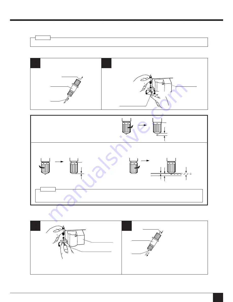
5-3  Installing/Removing a Blade

Do not touch the tip of the blade.  This could impair the cutting performance of the blade.

Installation

NOTICE

1

Insert blade into the blade holder until it
snaps into place with an audible click.

Blade

Push-pin

Blade holder

2

2) Support the tool-securing screw from below and install the blade

holder.

*  Insert the blade holder until the collar is flush with the carriage.

Tool-securing screw

1)  Loosen

3)  Tighten

Cutting carriage

Adjusting the
Cutter Blade

Blade adjustment may be necessary when:

-  cutting material whose carrier paper is thinner than the material itself
-  cutting material with no carrier paper

When cutting is performed after printing, the cap tip of the blade holder may scratch the printed surface.  If this is the case,
lengthen the cutter blade extension.

When stock vinyl film is to
be cut, tighten the cap all
the way (2.5 mm (about
0.1") of blade extension).

Tighten the cap until
gap is eliminated

Amount of cutter blade
extension: 2.5 mm (about
0.1") (maximum length)

1)

Gap

Amount of cutter blade
extension: 0 mm

Turn the cap as shown by the
arrow to align the tip of the
blade with the tip of the cap

2)

Amount of cutter
blade extension

Thickness of the carrier paper

Thickness of the
sheet portion

Turn the cap as
shown by the arrow

NOTICE

Turn the cap as
shown by the arrow

Содержание ColorCAMM PNC-5000

Страница 1: ...USER S MANUAL...

Страница 2: ...energy and if not installed and used in accordance with the instructions may cause harmful interference to radio communications However there is no guarantee that interference will not occur in a part...

Страница 3: ...to the Unit 2 To Ensure Correct Use 2 1 Checking Supplied Items 3 2 Part Names and Functions 3 2 1 Front View 3 2 2 Rear View 3 2 3 Operation Panel 4 3 Set up and Connections 5 4 What the PNC 5000 Can...

Страница 4: ...e safety of the area around the platen before switching on the power Do not install in an unstable or high location Do not install the machine on the edge of a table or it may fall Handle the blade wi...

Страница 5: ...aterial with these lines when loading Cutting Carriage The blade holder is mounted here Serial RS 232C Input Connector In a serial configuration connect the serial cable here This cable carries data t...

Страница 6: ...nt right edge of the material For more details see section 5 8 Removing and Reloading Printed Material for Cutting ALIGN POINT SET Key When material has been reloaded pressing this key sets the align...

Страница 7: ...upply voltage in within 10 of the machine s rated voltage 3 Set up and Connections When arranging setup space for the PNC 5000 make sure you have a space that is at least 905 mm 35 11 16 wide 500 mm 1...

Страница 8: ...tom SW 1 4 Sets the communication parameters for a serial connection When the PNC 5000 is connected to the computer through the serial port be sure that the communication parameters for SW 1 to SW 4 a...

Страница 9: ...e blade holder until the collar is flush with the carriage Tool securing screw 1 Loosen 3 Tighten Cutting carriage Adjusting the Cutter Blade Blade adjustment may be necessary when cutting material wh...

Страница 10: ...lose the cover Use your finger or a pen to take up excess slack in the ink ribbon Changing the ribbon cartridge while printing is in progress 1 Press the PAUSE key to stop operation of the PNC 5000 2...

Страница 11: ...r the sheet loading lever 2 3 Raise Sheet loading lever Press the SETUP key The SETUP LED lights up Removal To remove a portion that has been print or cut on roll material use the cutter tool included...

Страница 12: ...tically printed on the left and right areas at the front edge of the material Rear Front The ALIGN POINT SET LED lights up The BASE POINT SET LED lights up 2 Set the align point Use the cursor keys to...

Страница 13: ...ually increase the cutter force until you reach the optimum level 3 Then peel this off Peel off first Press the TEST key 5 11 Powering Off Do not switch off the power while the printing head is lowere...

Страница 14: ...POINT SET LED and ALIGN POINT SET LED light up This pattern indicates the current line pitch Use the table at right as a reference to press the and keys and make the desired line pitch setting After m...

Страница 15: ...tched to the material and the hardness of the blade This will extend the life of the blade Excessive cutter forces can cause the blade to wear out quickly Care should be taken 7 About the Printing Cut...

Страница 16: ...the power switch Is the PNC 5000 power on Turn on the power See 5 2 Powering On Is the unit in SETUP status the SETUP LED is lit If the SETUP LED is not illuminated make sure the material is loaded co...

Страница 17: ...puter Select the PNC 5000 as the output device Software Clean attractive printing is impossible Clean the printing head see 9 Care and Maintenance Is the printing head dirty If cleaning will not impro...

Страница 18: ...e that the left and right edges of the material do not touch the inner surfaces of the PNC 5000 during operation Such contact may damage the material and could also make it impossible to advance the m...

Страница 19: ...B3010896BE R3 1...

Отзывы: