19
3 Replacement of Main Parts
3
8
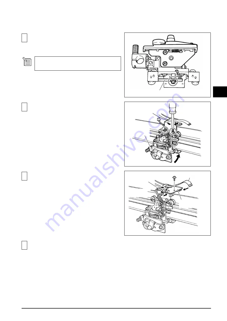
Fix the PINCH ROLL SENSOR.
9
Fix the TOOL CARRIAGE to the GUIDE RAIL.
10
Connect the PINCH ROLL SENSOR WIRE, SOLENOID
WIRE and CARRIAGE CABLE to the CARRIAGE
BOARD.
Then, fix it to the CARRIAGE BOARD STAY.
11
Carry out the following adjustments.
1. TOOL HEIGHT ADJUSTMENT
2. TOOL PRESSURE ADJUSTMENT
3. SEPARATING KNIFE ADJUSTMENT
PINCH ROLL SENSOR
TOOL
CARRIAGE
CARRIAGE
BOARD
CARRIAGE CABLE
PINCH ROLL
SENSOR WIRE
SOLENOID
WIRE
It is necessary to prepare a soldering iron or pin-
disconnector to fix PINCH ROLL SENSOR.
Содержание CAMM-1 PRO CM-300
Страница 4: ... MEMO ...
Страница 6: ...2 1 Structure Spare Parts 1 1 2 FRAME ...
Страница 28: ...24 3 Replacement of Main Parts 3 MEMO ...
Страница 62: ......
Страница 63: ...CM 500 400 300 ...


