R&S ENV4200
Introduction
User Manual 1107.2470.12 - 03
E-8
2.1 Front View
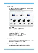
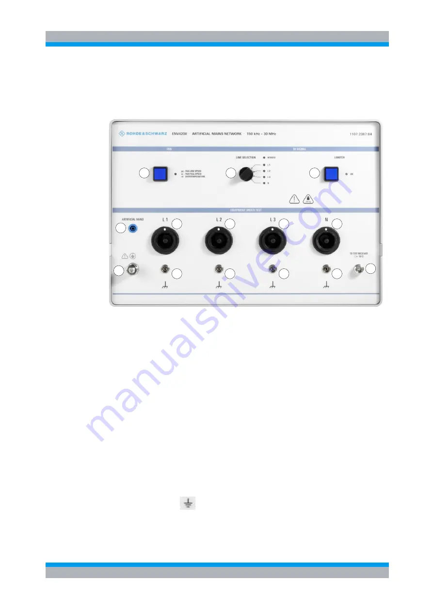
This illustration displays the front view of the R&S ENV4200. The individual elements
are described in detail in the following sections.
5
6
7
8
1
2
3
4
2
2
2
3
3
3
Fig. 1
Front view
1 = Connection to artificial hand (ARTIFICIAL HAND)
2 = Ground sockets
3 = MC high-current connector (L1, L2, L3, N)
4 = Button to power up the fan (FAN)
5 = Button to switch off the pulse limiter (LIMITER)
6 = Rotary switch to the phase selection (LINE SELECTION)
7 = Test receiver outlet (TO TEST RECEIVER)
8 = Protective earth terminal
2.1.1 Artificial Hand
4 mm banana socket to connect an artificial hand to imitate the influence of the hand of
the user during measurement of the interference voltage.
2.1.2 Ground Sockets (
)
4 mm banana socket to connect to the reference mass during calibration.

