R&S ENV4200
Introduction
User Manual 1107.2470.12 - 03
E-9
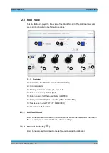
2.1.3 MC High Current Connector (L1, L2, L3, N)
MC panel connector for connection of the device under test for the interference voltage
measurement of single and three-phase devices under test with a star alternating
voltage of up 400 V (equivalent to a delta AC voltage of 690 V) and a DC voltage of up
to 690 V. The maximum continuous current for each phase is 200 A.
2.1.4 Fan
The fan can be manually operated to prevent damage caused by overheating. This is
done by pressing the momentary contact switch
.
The ventilation of the V-network is
automatically set to full speed at an internal housing temperature of approx. 50 °C and
the fan LED turns orange. If the coil temperature is > 100 °C, an acoustic alarm sounds
and the fan LED turns red.
2.1.5 Pulse Limiter (LIMITER)
The pulse limiter can be manually switched off by pressing the momentary contact
switch.
2.1.6 Phase Selection (LINE SELECTION)
Rotary switch for selecting the measuring path (L1, L2, L3 and N) of the V-network to
the test receiver. The measuring path LED which corresponds to the measuring path
selection is illuminated in green.
2.1.7 Test Receiver Outlet (TO TEST RECEIVER)
N socket (50
) for connecting to the test receiver.
2.1.8 Protective Earth Conductor Terminal (
)
M10 threaded bolt for connecting the protective earth conductor.

