RODCRAFT PNEUMATIC TOOLS GmbH
9
EN
2. Application and Function
• An air riveter is a tool to use blind rivets for positively joints.
• An air riveter is only suitable for blind rivets and has no other intended
use.
• Only use the air riveter as intended.
• Please observe the product safety information!
3. Inspection – Scope of Delivery
Open the packing and check the equipment for transport damage and that
all parts specified in the shipping documents are at hand. Before using the
equipment conduct a visual inspection in order to determine leakages,
damages, loose or missing parts.
Scope of delivery:
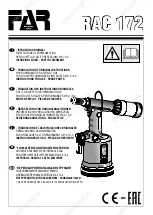
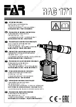
1 x Air riveter
RC6718Xi
1 x Chuck jaw
1 x Rivet seat bolt 6.4mm
1 x Rivet seat 4.8mm
1 x Rivet seat 4.0mm
2 x Chuck jaw sets (3 each) 3,5 mm
1 x Spring for chuck jaw spine
1 x Bottle hydraulic oil 42ml and syringe 5ml
1 x Allen key 3mm
4 x Jaw spanner SW 10/12 - 15/16 - 16/17 - 24/26
4. Implementation and Operation
•
Generally the safety guidelines are to be observed when working with
the equipment.
•
Position the air riveter in the location to be riveted after connecting the
air riveter to the air supply (observe safety precautions for connecting to
air supply).
•
To apply air pressure move the valve (Fig. 01) to “ON” position.
•
To activate the self-aspiration of the rivets and to set the desired suction
turn vacuum switch (Fig. 02) counter-clockwise. Now the rivets can be set
in any angle without having to hold them. Turn vacuum switch (Fig. 03)
clockwise in case self-aspiration is not wanted or to be reduced.
•
Maximum travel of the air riveter is achieved with operating pressure of
7 bar.
•
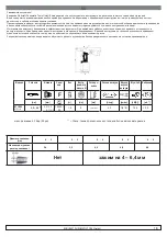
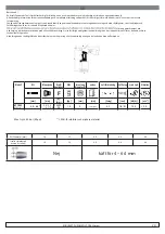
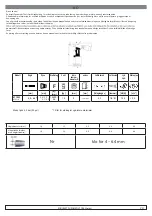
Always mount rivet seat corresponding to selected rivets. Ensure the
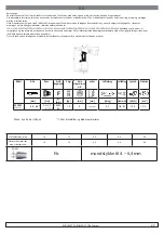
use of correct chuck jaws according to rivet size, as described on page
6. The appropriate tools are supplied; please see details in chapter
“Maintenance”.
•
Insert the blind rivet into the rivet seat, as shown in Fig. 04.
•
Press the trigger (Fig. 05) to pull the rivet (wear eye protection).
•
The rivet spine is automatically transported to the collection container
according to the set suction (Fig. 06).
•
In case the air riveter is used in a fi xed location for a longer period of
time then a suction hose can be used to collect the rivet spines (Fig. 07
and 08). Ensure appropriate suction power of the “
external suction
equipment
” (not supplied).
•
Move the valve (Fig. 01) to “OFF” position to discharge the air riveter if
not in use.
5. Maintenance
•
Before maintenance always move the ON/OFF valve to OFF position and
disconnect the tool from air supply!
•
Keep the tool clean and away from aggressive chemicals. Do not leave
the tool outdoors.
•
Apply one drop of machine oil to the chuck jaws every 10,000 cycles
(Fig. 09).
•
Unscrew the casing head with jaw spanner SW 24. Clean chuck jaws,
chuck jaw seats and casing head. Lubricate the chuck jaws (Fig. 09).
Assemble casing head in opposite sequence (do not overtighten casing
head).
•
Use jaw spanners SW 17 and SW 15 to unscrew or replace chuck jaws or
chuck jaw seats. Remove old chuck jaw from chuck jaw seat and replace
(Fig. 10).
•
Do not loosen or remove the lock nut! The distance of 75mm
between the tip of the chuck jaw and the casing must be kept, as
shown in Fig. 10. Damages due to noncompliance are excluded from
the warranty.
•
A complete oil change is not necessary!
Check and fill up hydraulic oil level if after approximately 100,000 cycles
the travel decreases or a blind rivet is not completely pulled. Observe the
safety precautions.
•
Place the air riveter upright. Unscrew the bolt of the fi ller hole with the
3mm Allen key (Fig. 11). Check the seal washer for damages and replace,
if necessary.
•
Fill hydraulic oil up to the bottom edge of the thread (Fig. 12).
•
Only use hydraulic oil (ISO VG22) approved by the manufacturer. Please
note: Never use brake fluid.
•
Do not hold the air riveter with open fi ller hole sidewise or upside down,
as air could enter the hydraulic system. In this case technical staff must
bleed the air riveter.
•
Only close the fi ller hole with the 3mm Allen key until no hydraulic oil is
leaking (Fig. 11). Remove excess hydraulic oil around the fi
ller hole.
•
Maintenance and repair of the equipment only by technical
maintenance staff.
6. Disposal
The disposal of this equipment must follow the legislation of the respective
country.
All damaged, badly worn or improperly functioning devices MUST BE
TAKEN OUT OF OPERATION.
Repair only by technical maintenance staff.
Use the equipment only for its intended use as described above, any
other use is expressly excluded! We are not responsible for injuries
and damage due to inappropriate use and misuse and/or
noncompliance of safety precautions; this is not covered by the
warranty.
Visit our Internet presence at www.rodcraft.com
Here you can also download our manuals.
With further questions contact your nearest Rodcraft branch or the
authorized dealer.
Содержание 676718
Страница 3: ...RODCRAFT PNEUMATIC TOOLS GmbH 3 RC6718Xi ...


