


70
Rockwell Automation Publication 7000L-UM301F-EN-P - March 2020
Chapter 2
Drive Installation
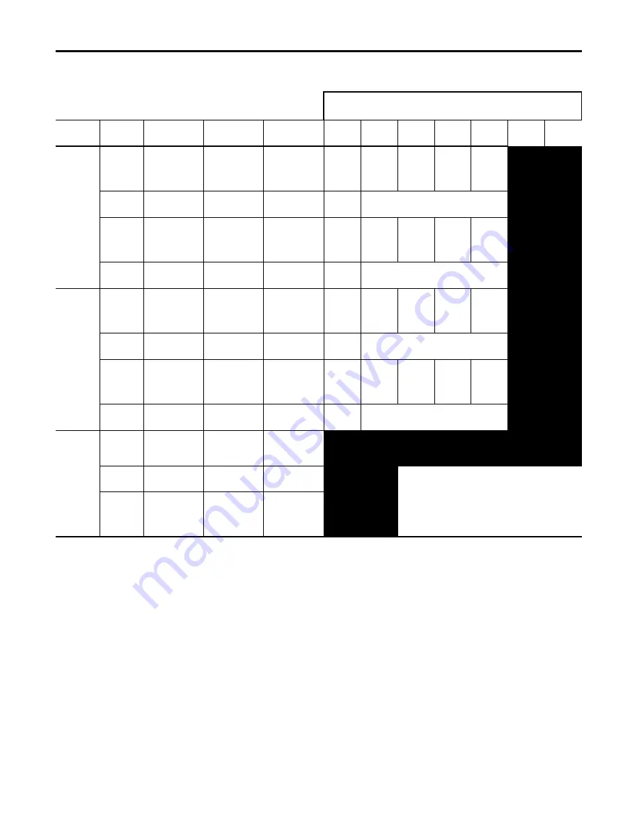
Table 4 - Wire Group Numbers
Belden 8760 - 18 AWG, twisted pair, shielded
Belden 8770 - 18 AWG, 3 conductor, shielded
Belden 9460 - 18 AWG, twisted pair, shielded
Belden 9463 - 24 AWG, twisted pair, shielded
Note 1:
Steel conduit or cable tray may be used for all PowerFlex 7000 Drive power or control wiring, and steel conduit is required for all
PowerFlex 7000 Drive signal wiring. All input and output power wiring, control wiring or conduit should be brought through the
drive conduit entry holes of the enclosure. Use appropriate connectors to maintain the environmental rating of the enclosure. The
steel conduit is REQUIRED for all control and signal circuits, when the drive is installed in European Union countries. The connection
of the conduit to the enclosure shall be on full 360 degree and the ground bond at the junction shall be less than 0.1 ohms. In EU
countries this is a usual practice to install the control and signal wiring.
Note 2:
Spacing between wire groups is the recommended minimum for parallel runs of 61 m (200 feet) or less.
Note 3:
The customer is responsible for the grounding of shields. On drives shipped after November 28/02, the shields are removed from
the drive boards. On drives shipped prior to November 28/02, all shields are connected at the drive end and these connections must
be removed before grounding the shield at the customer end of the cable. Shields for cables from one enclosure to another must be
grounded only at the source end cabinet. If splicing of shielded cables is required, the shield must remain continuous and insulated
from ground.
Note 4:
AC and DC circuits must be run in separate conduits or trays.
Note 5:
Voltage drop in motor leads may adversely affect motor starting and running performance. Installation and application
requirements may dictate that larger wire sizes than indicated in IEC / NEC guidelines are used.
For Tray:
Recommended spacing between different wire groups in the same tray.
For Conduit: Recommended spacing for wire groups in separate conduit – mm (inches)
Wire
Category
Wire
Group
Application
Signal Example
Recommended
Cable
Wire
Group
Power
1
Power
2
Control
3
Control
4
Signal
5
Signal
6
Power
1
AC Power
(> 600V AC)
2.3 kV, 3Ø
AC Lines
Per IEC / NEC
Local Codes and
Application
Requirements
In Tray
228.6
(9.00)
228.6
(9.00)
228.6
(9.00)
228.6
(9.00)
Between
Conduit
76.2 (3.00)
Between Conduit
2
AC Power
(TO 600V AC)
480V, 3Ø
Per IEC / NEC
Local Codes and
Application
Requirements
In Tray
228.6
(9.00)
228.6
(9.00)
152.4
(6.00)
152.4
(6.00)
Between
Conduit
76.2 (3.00)
Between Conduit
Control
3
115V AC
or 115V DC
Logic
Relay Logic
PLC I/O
Per IEC / NEC
Local Codes and
Application
Requirements
In Tray
228.6
(9.00)
152.4
(6.00)
228.6
(9.00)
152.4
(6.00)
115V AC
Power
Power Supplies
Instruments
Between
Conduit
76.2 (3.00)
Between Conduit
4
24V AC
or 24V DC
Logic
PLC I/O
Per IEC / NEC
Local Codes and
Application
Requirements
In Tray
228.6
(9.00)
152.4
(6.00)
152.4
(6.00)
228.6
(9.00)
Between
Conduit
76.2 (3.00) Between Conduit
Signal
5
Analog Signals
DC Supplies
5-24V DC
Supplies
Belden 8760
Belden 8770
Belden 9460
Digital
(Low Speed)
Power Supplies
TTL Logic Level
All signal wiring must be run in separate steel conduit.
A wire tray is not suitable.
The minimum spacing between conduits containing different
wire groups is 76.2 mm (3 inches).
6
Digital
(High Speed)
Pulse Train
Input Tachometer
PLC
Communications
Belden 8760
Belden 9460
Belden 9463
Содержание Allen-Bradley PowerFlex 7000
Страница 32: ...32 Rockwell Automation Publication 7000L UM301F EN P March 2020 Chapter 1 Overview of Drive Notes ...
Страница 90: ...90 Rockwell Automation Publication 7000L UM301F EN P March 2020 Chapter 2 Drive Installation Notes ...
Страница 174: ...174 Rockwell Automation Publication 7000L UM301F EN P March 2020 Chapter 4 Commissioning NOTES ...
Страница 264: ...264 Rockwell Automation Publication 7000L UM301F EN P March 2020 Chapter 4 Commissioning Notes ...
Страница 412: ...412 Rockwell Automation Publication 7000L UM301F EN P March 2020 Chapter 5 Component Definition and Maintenance ...
Страница 420: ...420 Rockwell Automation Publication 7000L UM301F EN P March 2020 Appendix A Catalog Number Explanation Notes ...
Страница 428: ...428 Rockwell Automation Publication 7000L UM301F EN P March 2020 Appendix C Meggering Notes ...
Страница 432: ...432 Rockwell Automation Publication 7000L UM301F EN P March 2020 Appendix D Preventative Maintenance Schedule Notes ...
Страница 433: ......


