


78
Rockwell Automation Publication 520-UM001K-EN-E - August 2021
Chapter 3 Programming and Parameters
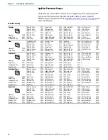
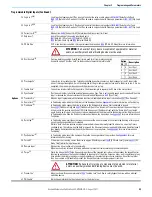
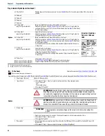
Basic Display Group
(continued)
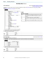
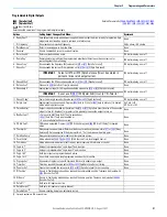
b012 [Control Source]
Related Parameter(s):
,
,
Active source of the Start Command and Frequency Command. Normally defined by the settings of
[Start Source x] and
Referencex].
See
Start and Speed Reference Control on page 48
for more information.
Values
Default:
Read Only
Min/Max:
0000/2165
Display:
0000
Start Command Source
Digit 1
1 = Keypad
2 = DigIn TrmBlk (Parameters
-
)
3 = Serial/DSI
4 = Network Opt
(1)
5 = EtherNet/IP
(2)
(1) Select this setting if using the optional PowerFlex 25-COMM-E2P, 25-COMM-D,
or 25-COMM-P adapters as the Start source and/or Frequency source.
(2) Setting is specific to PowerFlex 525 drives only.
Frequency Command Source
Digit 2 & 3
00 = Other
01 = Drive Pot
02 = Keypad
03 = Serial/DSI
04 = Network Opt
(1)
05 = 0-10V Input
06 = 4-20mA Input
07 = Preset Freq (Parameters
08 = Anlg In Mult
(2)
09 = MOP
10 = Pulse Input
11 = PID1 Output
12 = PID2 Output
(2)
13 = Step Logic (Parameters
)
(1)
14 = Encoder
(2)
15 = EtherNet/IP
(2)
16 = Positioning
(2)
Frequency Command Source
Digit 4
0 = Other (Digit 2 & 3 are used. Digit 4 is not shown.)
1 = Jog
2 = Purge
Not Used
Example
Display reads... Description
2004
Start source comes from Network Opt and Frequency source is Purge.
113
Start source comes from Serial/DSI and Frequency source comes from
PID1 Output.
155
Start source and Frequency source comes from EtherNet/IP.
052
Start source comes from DigIn TrmBlk and Frequency source from 0…10V
Input.
011
Start source comes from Keypad and Frequency source comes from Drive
Pot.
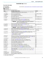
b013 [Contrl In Status]
Related Parameter(s):
State of the digital terminal blocks 1...3 and DB transistor.
Values
Default:
Read Only
Min/Max:
0000/1111
Display:
0000
IMPORTANT
Actual control commands may come from a source other than the control terminal block.
1 = Closed State, 0 = Open State
DigIn TBlk 1
Digit 1
DigIn TBlk 2
Digit 2
DigIn TBlk 3
Digit 3
DB Trans On
(1)
Digit 4
(1) The DB Transistor “on” indication must have a 0.5 s hysteresis. It will turn
on and stay on for at least 0.5 s every time the DB transistor is turned on.
Not Used
Содержание Allen-Bradley PowerFlex 520 Series
Страница 8: ...8 Rockwell Automation Publication 520 UM001K EN E August 2021 Table of Contents Notes ...
Страница 68: ...68 Rockwell Automation Publication 520 UM001K EN E August 2021 Chapter 2 Start Up Notes ...
Страница 156: ...156 Rockwell Automation Publication 520 UM001K EN E August 2021 Chapter 3 Programming and Parameters Notes ...
Страница 202: ...202 Rockwell Automation Publication 520 UM001K EN E August 2021 Appendix B Accessories and Dimensions Notes ...
Страница 236: ...236 Rockwell Automation Publication 520 UM001K EN E August 2021 Appendix F PID Set Up Notes ...
Страница 262: ...262 Rockwell Automation Publication 520 UM001K EN E August 2021 Appendix J PowerFlex 525 PM Motor Configuration Notes ...
Страница 270: ...270 Rockwell Automation Publication 520 UM001K EN E August 2021 Index Notes ...