


106
Rockwell Automation Publication 520-UM001K-EN-E - August 2021
Chapter 3 Programming and Parameters
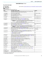
Logic Group
StepLogic Inputs
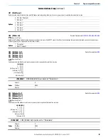
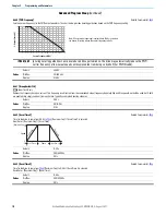
L180 [Stp Logic 0]
L182 [Stp Logic 2]
L184 [Stp Logic 4]
L186 [Stp Logic 6]
L181 [Stp Logic 1]
Related Parameter(s):
L183 [Stp Logic 3]
L185 [Stp Logic 5]
L187 [Stp Logic 7]
Stop drive before changing this parameter.
PowerFlex 525 only.
Values
Default:
00F1
Min/Max:
0000/FAFF
Display
0001
See
for more information on applying StepLogic® function and Position StepLogic application.
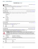
Parameters L180...L187 are only active if
, or
[Speed Referencex] is set to 13 “Step Logic” or 16 “Positioning”. These parameters can be used to create a
custom profile of frequency commands. Each “step” can be based on time, status of a Logic input or a combination of time and the status of a Logic input.
Digits 1...4 for each [Stp Logic x] parameter must be programmed according to the desired profile. A Logic input is established by setting a digital input, parameters
,
[DigIn TermBlk xx] to 24 “Logic In 1” and/or 25 “Logic In 2” or by using Bits 6 and 7 of
[Enh Control Word].
A time interval between steps can be programmed using parameters
...
[Stp Logic Time x]. See the table below for related parameters.
The speed for any step is programmed using parameters
...
[Preset Freq x].
The position for any step is programmed using parameters
...
[Step Units x].
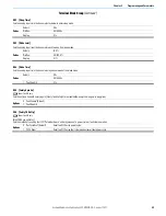
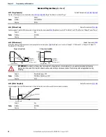
How StepLogic Works
The StepLogic sequence begins with a valid start command. A normal sequence always begins with L180 [Stp Logic 0].
Digit 1: Logic for next step
This digit defines the logic for the next step. When the condition is met the program advances to the next step. Step 0 follows Step 7. Example: Digit 1 is set to 3. When
“Logic In 2” becomes active, the program advances to the next step.
Digit 2: Logic to jump to a different step
For all settings other than F, when the condition is met, the program overrides Digit 0 and jumps to the step defined by Digit 3.
Digit 3: Different step to jump
When the condition for Digit 2 is met, this digit setting determines the next step or to end the program.
Digit 4: Step settings
This digit defines additional characteristics of each step.
Any StepLogic parameter can be programmed to control a relay or opto output, but you can not control different outputs based on the condition of different StepLogic
commands.
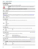
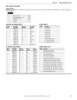
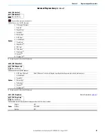
PF 525
Step StepLogic Parameter Related Preset Frequency Parameter
(Can be activated independent of StepLogic Parameters)
Related StepLogic Time Parameter
(Active when L180...L187 Digit 1 or 2 are set to 1, b, C, d or E)
0
L180 [Stp Logic 0]
A410 [Preset Freq 0]
L190 [Stp Logic Time 0]
1
L181 [Stp Logic 1]
A411 [Preset Freq 1]
L191 [Stp Logic Time 1]
2
L182 [Stp Logic 2]
A412 [Preset Freq 2]
L192 [Stp Logic Time 2]
3
L183 [Stp Logic 3]
A413 [Preset Freq 3]
L193 [Stp Logic Time 3]
4
L184 [Stp Logic 4]
A414 [Preset Freq 4]
L194 [Stp Logic Time 4]
5
L185 [Stp Logic 5]
A415 [Preset Freq 5]
L195 [Stp Logic Time 5]
6
L186 [Stp Logic 6]
A416 [Preset Freq 6]
L196 [Stp Logic Time 6]
7
L187 [Stp Logic 7]
A417 [Preset Freq 7]
L197 [Stp Logic Time 7]
Step StepLogic Position Parameter
0
L200 [Step Units 0] & L201 [Step Units F 0]
1
L202 [Step Units 1] & L203 [Step Units F 1]
2
L204 [Step Units 2] & L205 [Step Units F 2]
3
L206 [Step Units 3] & L207 [Step Units F 3]
4
L208 [Step Units 4] & L209 [Step Units F 4]
5
L210 [Step Units 5] & L211 [Step Units F 5]
6
L212 [Step Units 6] & L213 [Step Units F 6]
7
L214 [Step Units 7] & L215 [Step Units F 7]
Содержание Allen-Bradley PowerFlex 520 Series
Страница 8: ...8 Rockwell Automation Publication 520 UM001K EN E August 2021 Table of Contents Notes ...
Страница 68: ...68 Rockwell Automation Publication 520 UM001K EN E August 2021 Chapter 2 Start Up Notes ...
Страница 156: ...156 Rockwell Automation Publication 520 UM001K EN E August 2021 Chapter 3 Programming and Parameters Notes ...
Страница 202: ...202 Rockwell Automation Publication 520 UM001K EN E August 2021 Appendix B Accessories and Dimensions Notes ...
Страница 236: ...236 Rockwell Automation Publication 520 UM001K EN E August 2021 Appendix F PID Set Up Notes ...
Страница 262: ...262 Rockwell Automation Publication 520 UM001K EN E August 2021 Appendix J PowerFlex 525 PM Motor Configuration Notes ...
Страница 270: ...270 Rockwell Automation Publication 520 UM001K EN E August 2021 Index Notes ...