


A-2
DriveLogix5730 Controller Specifications
DriveLogix5730
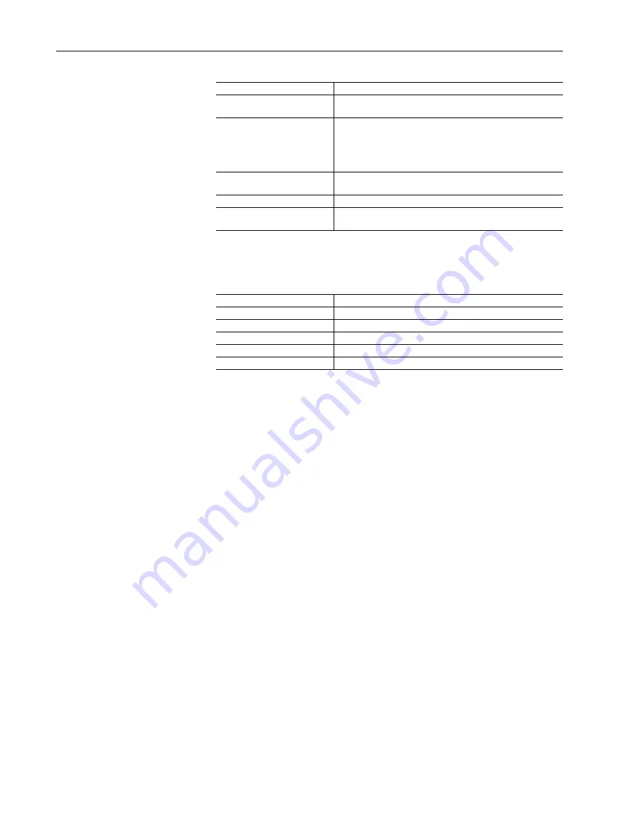
Certifications
Real-Time Clock Accuracy
Certification
Description
c-UL-us
UL Listed for Class I, Division 2 Group A,B,C,D Hazardous
Locations, certified for U.S. and Canada
CE
(1)
(1)
See the Product Certification link at www.ab.com for Declarations of Conformity, Certificates, and other
certification details.
European Union 89/336/EEC EMC Directive, compliant with:
•
EN 50082-2; Industrial Immunity
•
EN 61326; Meas./Control/Lab., Industrial Requirements
•
EN 61000-6-2; Industrial Immunity
•
EN 61000-6-4; Industrial Emissions
C-Tick
Pending at time of printing
Australian Radiocommunications Act, compliant with:
•
AS/NZS CISPR 11; Industrial Emissions
EtherNet/IP
ODVA conformance tested to EtherNet/IP specifications
c-UL-us
UL Listed for Class I, Division 2 Group A,B,C,D Hazardous
Locations, certified for U.S. and Canada
Ambient °C
Accuracy
0
°
C
+54 to -56 seconds/month
+25
°
C
+9 to -124 seconds/month
+40
°
C
-84 to -234 seconds/month
+55
°
C
-228 to -394 seconds/month
+60
°
C
-287 to -459 seconds/month
Содержание Allen-Bradley DriveLogix 5730
Страница 6: ...4 ...
Страница 10: ...p 4 Notes ...
Страница 22: ...1 12 What is DriveLogix5730 Notes ...
Страница 68: ...3 20 Placing and Configuring Local I O Notes ...
Страница 131: ...Communicating with Devices on an EtherNet IP Link 6 33 This example shows DriveLogix1 producing tagA and consuming tagB ...
Страница 134: ...6 36 Communicating with Devices on an EtherNet IP Link Notes ...
Страница 155: ...Communicating with Devices on an ControlNet Link 7 21 This example shows DriveLogix1 producing tagA and consuming tagB ...
Страница 182: ...9 10 Communicating with Devices on a DH485 Link Notes ...
Страница 200: ...B 10 Access Procedures Notes ...
Страница 205: ......
Страница 206: ......
Страница 207: ......
Страница 209: ...Allen Bradley User Manual DriveLogix 5730 ...


