


Rockwell Automation Publication 1606-RM124A-EN-P - September 2021
19
DC/DC Converter - 48V/48V, 5 A, 240 W Reference Manual
The buffer module does not require any control wiring. It can be added in
parallel to the load circuit at any given point.
One buffer module can deliver 20 A additional current. Buffer modules can be
added in parallel to increase the output ampacity or the hold-up time.
Peak Current Capability
The unit can deliver peak currents (up to several milliseconds), which are
higher than the specified short-term currents.
This capability helps to start current-demanding loads. Solenoids, contactors,
and pneumatic modules often have a steady state coil and a pick-up coil. The
inrush current demand of the pick-up coil is several times higher than the
steady-state current and usually exceeds the nominal output current. The
same situation applies when starting a capacitive load.
The peak current capability also achieves the safe operation of subsequent
circuit breakers of load circuits. The load branches are often individually
protected with circuit breakers or fuses. If there is a short or an overload in one
branch circuit, the fuse or circuit breaker need a certain amount of overcurrent
to open in a timely manner. This avoids voltage loss in adjacent circuits.
The extra current (peak current) is supplied by the power converter and the
built-in large sized output capacitors of the power supply. The capacitors get
discharged during such an event, which causes a voltage dip on the output.
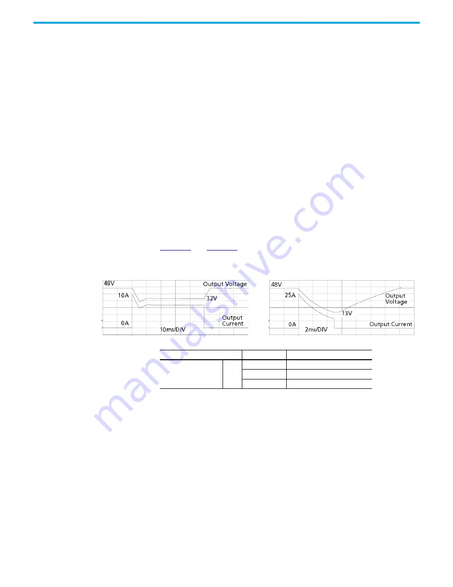
show two typical voltage dips.
Output Circuit Breakers
Standard miniature circuit breakers (MCB’s or UL 1077 circuit breakers) are
commonly used for AC-supply systems and can also be used on 48V branches.
MCBs are designed to protect wires and circuits. If the ampere value and the
characteristics of the MCB are adapted to the wire size that is used, the wiring
is considered as thermally safe, regardless of whether the MCB opens or not.
To avoid voltage dips and undervoltage situations in adjacent 24V branches
that are supplied by the same source, a fast (magnetic) tripping of the MCB is
desired. A quick shutdown within 10 ms is necessary, corresponding roughly to
the ride-through time of programmable logic controllers (PLCs). This
shutdown requires power supplies with high current reserves and large output
capacitors. Furthermore, the impedance of the faulty branch must be
sufficiently small for the current to flow. The best current reserve in the power
supply does not help if Ohm’s Law does not permit current flow. The following
table has typical test results showing which B- and C-Characteristic MCB’s
magnetically trip depending on the wire cross section and wire length.
Figure 24 - 10 A Resistive Peak Load for 50 ms, Typ
(2x the Nominal current)
Figure 25 - 25 A Resistive Peak Load for 5 ms, Typ
(5x the Nominal current)
Attribute
Values
Notes
Peak current voltage dips
Typ
48V dips to 32V
At 10 A for 50 ms and resistive load
48V dips to 28V
At 25 A for 2 ms and resistive load
48V dips to 13V
At 25 A for 5 ms and resistive load


