Rockwell Automation 2711PC- T6C20D Скачать руководство пользователя страница 48

48

Publication 2711PC-UM001A-EN-P - March 2009

Chapter 4

        Configuring the Terminal

Delete Log Files from Terminal

You can delete log files, alarm history files, and alarm status files from 
the System Default location on the terminal.

1.

Select Terminal Settings>File Management>Delete Files>Delete 
Log Files.

You are asked to confirm the deletion of the files.

2.

Select Yes or No.

Only log files in the System Default location are deleted.

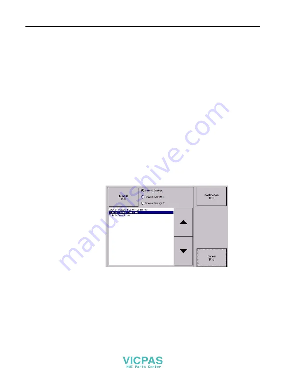
Copy an Application File or Font File

The procedure for copying an application .MER file or a font file from 
one storage location on the terminal to another is the same. 

1.

Select Terminal Settings>File Management>Copy Files>Copy 
Applications or Copy Fonts.

2.

Press the Source button to choose the location of the application 
or font file you want to copy.

Internal Storage - the internal CompactFlash in the terminal.

External Storage 1 - the external CompactFlash card loaded in 
the card slot of the terminal.

External Storage 2 - for future use.

3.

Select a file from the storage location. 

4.

Press the Destination button on the same screen.

List of files stored 
in  CompactFlash 
of terminal.

Содержание 2711PC- T6C20D

Страница 1: ...User Manual Catalog Numbers 2711PC K4M20D 2711PC B4C20D 2711PC T6M20D 2711PC T6C20D 2711PC T10C4D1 PanelView Plus Compact Terminals ...

Страница 2: ...e of information circuits equipment or software described in this manual Reproduction of the contents of this manual in whole or in part without written permission of Rockwell Automation Inc is prohibited Throughout this manual when necessary we use notes to make you aware of safety considerations Allen Bradley PanelView Plus PanelView Plus Compact FactoryTalk View FactoryTalk View ME FactoryTalk ...

Страница 3: ... 600 Terminal in a Panel 18 Mount the 1000 Terminal in a Panel 20 Product Dimensions 22 Chapter 3 Connecting Power Chapter Objectives 23 Wiring and Safety Guidelines 23 Removing and Installing the Power Terminal Block 24 Connecting Power 26 Resetting the Terminals 29 Chapter 4 Configuring the Terminal Chapter Objectives 31 Accessing Configuration Mode 31 Loading an Application 35 Running an Applic...

Страница 4: ...tives 75 Required Tools 75 Precautions 75 Replacing the Battery 76 Replacing the Backlight 79 Using an External CompactFlash Card 81 Removing the Product ID Label 82 Replacing the Bezel 83 Cleaning the Display Window 85 Chapter 6 Terminal Connections Chapter Objectives 87 Cables for Runtime Communication 87 Communication Port Isolation 88 USB Ports 89 Serial Connections 90 Ethernet Connections 93 ...

Страница 5: ...hecking Terminal Components 111 Ethernet Connection 114 Hardware Compatibility 115 Application Does Not Load 115 Application Does Not Run 116 Configuration Mode Access 116 Appendix A Specifications Electrical 117 Environmental 117 Display 118 Mechanical 118 General 119 Agency Certifications 119 Appendix B USB Devices Compatible USB Devices 121 Appendix C Available Fonts Download Fonts to Terminal ...

Страница 6: ...6 Publication 2711PC UM001A EN P March 2009 Table of Contents ...

Страница 7: ... cutout template Installation instructions Additional Resources The table lists resources available for the PanelView Plus terminals You can view or download publications at http literature rockwellautomation com To order paper copies of technical documentation contact your local Rockwell Automation distributor or sales representative Resource Description PanelView Plus 400 and 600 Terminals Insta...

Страница 8: ...8 Publication 2711PC UM001A EN P March 2009 Preface ...

Страница 9: ...Limited number of displays and alarms in the FactoryTalk View Machine Edition ME application and runtime software FactoryTalk ViewPoint software is not supported Primary HMI for CompactLogix controllers Catalog Number Explanation The table provides catalog number configurations for the PanelView Plus Compact terminals TIP Applications created for PanelView Plus Compact terminals are referred to as...

Страница 10: ...Ethernet communication only If using RSLinx Enterprise only serial DF1 serial DH485 and Ethernet drivers are supported Hardware Configurations The terminal configurations are fixed and do not support communication modules The 1000 touch terminal has a fixed display module and logic module that cannot be replaced Software Requirements Version FactoryTalk View Studio 5 1 or later RSLinx Enterprise 1...

Страница 11: ...eys Use the arrow keys for navigation Use the Alt arrow keys to activate home end page up and page down functions ATTENTION Use a finger or gloved finger to operate the keypad To operate the touch screen use your finger gloved finger or plastic stylus with a minimum tip radius of 1 3 mm 0 051 in Using other object or tool may damage the touch screen or keypad IMPORTANT The PanelView Plus Compact t...

Страница 12: ...ch cutout Cables Cat No Description 2711 NC13 RS 232 operating programming cable 9 pin D shell to 9 pin D shell 5 m 16 4 ft 2711 NC14 RS 232 operating programming cable 9 pin D shell to 9 pin D shell 10 m 32 7 ft 2711 NC17 Remote RS 232 serial cable 9 pin D shell to 9 pin D shell 2711 NC21 RS 232 operating cable 9 pin D shell to 8 pin mini DIN 5 m 16 4 ft 2711 NC22 RS 232 operating cable 9 pin D s...

Страница 13: ...zardous locations The following statement applies to use in hazardous locations The terminals have a temperature code of T4 when operating in a 55 C 131 F maximum ambient temperature Do not install the terminals in environments where atmospheric gases have ignition temperatures less than 135 C 275 F WARNING Explosion Hazard Substitution of components may impair suitability for hazardous locations ...

Страница 14: ...ng apparatus must have nonincendive circuit parameters conforming with Table 2 Table 1 PanelView Plus Compact USB Port Circuit Parameters Display Size Voc Isc Ca La Groups A and B Groups C and D Groups A and B Groups C and D 400 and 600 Series C or later 5 25V DC 1 68 A 10 µF 10 µF 3 5 µH 15 µH 1000 5 25V DC 1 68 A 10 µF 10 µF 15 µH 15 µH Table 2 Required Circuit Parameters for the USB Peripheral ...

Страница 15: ...501 10 B 3 of the National Electrical Code NEC ANSI NFPA 70 or other local codes as applicable This associated nonincendive field wiring apparatus has not been evaluated for use in combination with another associated nonincendive field wiring apparatus Symbol Definitions Voc Open circuit voltage of the host USB port Isc Maximum output current of the host USB port Vmax Maximum applied voltage ratin...

Страница 16: ...s This equipment is supplied as open type equipment It must be mounted within an enclosure that is suitably designed for those specific environmental conditions that will be present and appropriately designed to prevent personal injury resulting from accessibility to live parts The interior of the enclosure must be accessible only by the use of a tool The terminals meet specified NEMA Type and IEC...

Страница 17: ...er devices in the enclosure The ambient temperature around the terminals must be between 0 55 C 32 131 ºF Cutout Dimensions Use the full size template shipped with your terminal to mark the cutout dimensions Clearance Area 400 and 600 Terminals 1000 Terminal Top 51 mm 2 in 51 mm 2 in Bottom 102 mm 4 in 51 mm 2 in Side 1 1 Minimum side clearance for insertion of memory card and cable wiring is 102 ...

Страница 18: ... This gasket forms a compression type seal Do not use sealing compounds 3 Place the terminal in the panel cutout If installing the terminal in an existing 550 panel cutout align the terminal with the center of the cutout for best gasket sealing 4 Insert all mounting levers into the mounting slots on the terminal ATTENTION Disconnect all electrical power from the panel before making the panel cutou...

Страница 19: ...Levers Flat Side of Lever 6 Levers 2 4 6 5 1 3 Notch 6 1 Alignment Marks Rotate lever until notch in lever aligns with proper alignment mark on terminal 1 4 3 2 4 Levers Lever Position Panel Thickness Range Typical Gauge 1 1 52 2 01 mm 0 060 0 079 in 16 2 2 03 2 64 mm 0 08 0 104 in 14 3 2 67 3 15 mm 0 105 0 124 in 12 4 3 17 3 66 mm 0 125 0 144 in 10 5 3 68 4 16 mm 0 145 0 164 in 8 9 6 4 19 4 75 mm...

Страница 20: ...erminal sealing gasket is properly positioned on the terminal This gasket forms a compression type seal Do not use sealing compounds 3 Place the terminal in the panel cutout ATTENTION Disconnect all electrical power from the panel before making the panel cutout Make sure the area around the panel cutout is clear Take precautions so metal cuttings do not enter any components already installed in th...

Страница 21: ...he mounting clips screws to a torque of 0 90 1 1 N m 8 10 lb in by using the specified sequence making sure not to overtighten Mounting Clip Slot Mounting Clip ATTENTION Tighten the mounting clips to the specified torque to provide a proper seal and to prevent damage to the product Allen Bradley assumes no responsibility for water or chemical damage to the product or other equipment within the enc...

Страница 22: ...imensions for each terminal are in mm in PanelView Plus 400 Keypad or Keypad Touch Dimensions PanelView Plus Compact 600 Touch Dimensions PanelView Plus Compact 1000 Touch Dimensions 152 6 0 185 7 28 60 2 35 90 3 54 71 2 81 154 6 08 185 7 28 152 6 0 98 3 86 71 2 81 154 6 08 68 2 68 329 12 97 55 2 18 248 9 7 ...

Страница 23: ...power by a fuse or circuit breaker rated at no more than 15 A route incoming power to the device by a separate path from the communication lines cross power and communication lines at right angles if they must cross Communication lines can be installed in the same conduit as low level DC I O lines less than 10V shield and ground cables appropriately to avoid electromagnetic interference EMI Ground...

Страница 24: ...he terminal block access slot 2 Gently pry the terminal block away from terminal to release the locking mechanism WARNING Explosion Hazard Substitution of components may impair suitability for hazardous locations Do not disconnect equipment unless power has been switched off and area is known to be nonhazardous Do not connect or disconnect components unless power has been switched off All wiring m...

Страница 25: ...ack to the vertical position to snap in locking tab PanelView Plus Compact 1000 Terminals Follow these steps to remove the terminal block 1 Loosen the two screws that secure the terminal block 2 Gently pull the terminal block away from the connector Follow these steps to install the terminal block 1 Reattach the terminal block to the connector until seated 2 Tighten the two screws that secure the ...

Страница 26: ...he power supply must be isolated from the input and not connected to earth ground The non isolated power supply does not provide galvanic isolation A Class 2 or Safety Extra Low Voltage SELV isolated power supply with a 24V DC nominal output voltage is required to power the terminal Terminal Wire Type Dual wire Gauge 1 Single wire Gauge Terminal Screw Torque 400 and 600 Stranded or solid Cu 90 C 1...

Страница 27: ... to Communication Port Isolation page 88 for details IMPORTANT The earth ground connection to ground is mandatory This connection is required for noise immunity reliability and Electromagnetic Compliance EMC with the European Union EU EMC directive for CE mark conformance and is required for safety by Underwriters Laboratory Terminal Symbol Wire Type Wire Gauge Terminal Screw Torque 400 and 600 St...

Страница 28: ...functional earth ground terminal on the input power terminal block On the 1000 terminal secure the earth ground wire to the earth ground terminal screw at the bottom of the display 4 Apply 24V DC power to the terminal WARNING Explosion Hazard Do not disconnect equipment unless power has been switched off and area is known to be nonhazardous Disconnect all power before installing or replacing compo...

Страница 29: ...figured for your terminal Refer to page 60 for information on startup options Refer to Chapter 8 Troubleshooting for a list of startup information and error messages On 400 and 600 terminals press the reset switch with your finger or a nonconductive object On 1000 terminals insert a thin nonconductive probe into the hole marked reset and press the switch Reset Reset Switch ATTENTION Use a noncondu...

Страница 30: ...30 Publication 2711PC UM001A EN P March 2009 Chapter 3 Connecting Power ...

Страница 31: ...ard software FactoryTalk View ME Station to perform and configure terminal operations When you reset or start the terminal you automatically enter Configuration mode unless your MER application is automatically set to run on startup To access Configuration mode from a running application press the Goto Configuration Mode button The application stops running but is still loaded IMPORTANT To access ...

Страница 32: ...under Current Application An application must be loaded before you can run it Application Settings F3 Opens a menu of application specific configuration settings Terminal Settings F4 Opens a menu of options to configure non application specific terminal settings Delete Log Files Before Running F5 Toggles between Yes and No If you select Yes all data log files alarm history and alarm status file wi...

Страница 33: ... the button or in some cases the corresponding key on the keypad If a mouse is attached click a button In addition to operation specific buttons most screens have a combination of these buttons Navigation Buttons Description Returns to the previous screen Accepts modified values and returns to previous screen Cancels the current operation without saving any changes Moves highlight up or down a lis...

Страница 34: ...ed click a key 2 Press the Select button to copy the character to the display area 3 Press Enter when done to exit the input panel Display Area Character Keyboard Controls PanelView Plus Input Panel Controls Function SHF Switches keys between their shifted and unshifted state The initial default is shifted CAPS Switches keys between lowercase and uppercase characters The initial default is lowerca...

Страница 35: ...sked if you want to replace the terminal s communication configuration with the communication settings in the application 5 Select Yes or No If you select Yes any changes to the device addresses or driver properties in the RSLinx Communication screen will be lost The name of the currently loaded application will appear at the top of the main configuration screen If you try to load a regular Machin...

Страница 36: ...nning diagnostics Display Shows the temperature of the display sets the intensity of the backlight and enables disables the screen saver File Management Copies or deletes application files or font files from a storage location Font Linking Links a font file to a base font loaded on the terminal Input Devices Configures settings for the keypad touch screen or attached keyboard and mouse Networks an...

Страница 37: ...communication protocol used by your MER application Edit the device address of the controller on the network KEPServer Serial Port ID s To access the KEPServer Serial Port ID s screen you must have KEPServer Enterprise installed on your terminal Otherwise you will get an error message when accessing this screen If you plan on using KEPServer Enterprise and serial communication you must specify whi...

Страница 38: ...see a tree view of installed communication cards and network configurations 2 Select the communication card installed on your terminal 3 Press the Edit Driver button to view the current properties for the communication driver 4 Select the property you want to modify then press the Edit button 5 Modify the setting and then press the Enter button You return to the previous screen with the newly ente...

Страница 39: ... of stop bits used 1 or 2 Ack Timeout Ack Poll timeout value in ms 20 60 000 ms Max Retries Maximum number of retries before the serial driver fails 0 255 Station Station number based on a specific device PLC_CH0 0 77 octal KF2 0 77 octal SLC_CH0 0 31 KF3 0 31 KFC 1 99 KFC15 1 99 AC_CH0 0 255 Baud Rate Data rate at which serial driver communicates The baud rate is automatically configured if Use A...

Страница 40: ...evice node 2 Press the Edit Device button to view the device name and current address of the logic controller 3 Press the Device Address button to modify the address The input panel opens with the current address 4 Use the Input Panel to modify the address and then press the Enter button You return to the previous screen with the new address 5 Press OK IMPORTANT Modified settings do not take effec...

Страница 41: ...on for your terminal 1 Select Terminal Settings Networks and Communications Network Connections Device Name 2 Press the Device Name button to enter or edit the device name 3 Press the Device Description button to enter or edit the description for the device 4 Press OK Field Description Valid Values Device Name 1 1 Check with your network administrator to determine a valid device name Name that ide...

Страница 42: ... the terminal Follow these steps to view or enter an IP address for your terminal 1 Select Terminal Settings Networks and Communications Network Connections Network Adapters 2 Press the IP Address button to view or modify the IP address 3 Press the DHCP button to enable or disable DHCP assignment of addresses 4 Press the IP address Subnet Mask and Gateway buttons then enter the appropriate informa...

Страница 43: ...et Mask and Gateway The fields are disabled If DHCP is set to No you can enter the IP address Subnet Mask and Gateway address Yes default No IP Address A unique address identifying the terminal on the Ethernet network xxx xxx xxx xxx 000 000 000 000 default Range of values for the first set of decimal numbers is 1 255 unless all fields are set to 000 The range of values for the last three sets of ...

Страница 44: ...e name server address 1 Select Terminal Settings Networks and Communications Network Connections Network Adapters 2 Press a button to enter a name server address 3 Press OK when done Field Description Valid Values Primary DNS The address of the primary DNS resolver xxx xxx xxx xxx Secondary DNS The address of the secondary DNS resolver xxx xxx xxx xxx Primary WINS The address of the primary WINS r...

Страница 45: ...nformation provided by your network administrator 3 Press OK when done Configuring Diagnostics You can configure diagnostics for the current computer To access the diagnostic screen select Terminal Settings Diagnostic Setup from the main screen The screen shows a tree view of diagnostic nodes Field Description Valid Values User Name Identifies the user to the network 70 characters max Password Cha...

Страница 46: ...reen lets you access these screens Remote Log FactoryTalk View Diagnostics List Each of the above screens shows a list of messages that can be sent to that destination The list shows the On Off status of each message type Use the On Off button to turn a message type on or off A message type is enabled if it has a checked box Field Description Valid Values Address Address of the remote Windows 2000...

Страница 47: ...ation file or a font file from the terminal is the same except for the type of file you are deleting 1 Select Terminal Settings File Management Delete Files Delete Applications or Delete Fonts 2 Press the Source button to choose the storage location of the application or font file you want to delete Internal Storage the internal CompactFlash in the terminal External Storage 1 the external CompactF...

Страница 48: ...le or Font File The procedure for copying an application MER file or a font file from one storage location on the terminal to another is the same 1 Select Terminal Settings File Management Copy Files Copy Applications or Copy Fonts 2 Press the Source button to choose the location of the application or font file you want to copy Internal Storage the internal CompactFlash in the terminal External St...

Страница 49: ...ternal Storage 1 the external CompactFlash card loaded in the card slot of the terminal External Storage 2 for future use 6 Press the Copy button to copy the selected application or font file to the selected destination If the file exists you will receive a warning and will be asked if you want to overwrite the existing application 7 Select Yes or No TIP FactoryTalk View ME software looks for MER ...

Страница 50: ...ns If the internal temperature of the product is below 10 C 50 F the backlight is set to overdrive or the full rated current setting for at least five minutes If the internal temperature is at or above 60 C 50 F the backlight is set to underdrive 40 or less of full brightness This reduces heat generation from the backlight Temperature monitoring begins when the terminal powers on or when the backl...

Страница 51: ...3 Press OK when done Adjust the Display Intensity You can view or modify the intensity of the terminal backlight You can use the default intensity of 100 or you can set the intensity for runtime operations 1 Select Terminal Settings Display Display Intensity 2 Press the Startup Intensity button to switch between the Default intensity and the Runtime intensity If you choose Runtime the startup scre...

Страница 52: ...al Settings Display Screen Saver 2 Press the Screen Saver button to select an idle timeout for activating the screen saver To disable the screen saver select the Disabled option 3 Increase or decrease the brightness intensity of the screen saver by pressing the up and down cursor buttons 4 Press the Advanced Settings button to access the bitmap option Select the Screen Saver Image button to enable...

Страница 53: ... on the terminal select Terminal Settings Font Linking Arial Courier New Tahoma Times New Roman Show Links F1 Close F8 Courier New MS Mincho Tahoma Times New Roman Add Fonts F1 Close F8 Close F8 Delete Link F1 Edit Link F2 Base font Arial Link MS Mincho External storage 1 MSMINCHO TTC List of fonts loaded on the terminal Shows the location and name of the font that is linked to the base font used ...

Страница 54: ...minal keypad or for keys on an attached keyboard 1 Select Terminal Settings Input Devices Keyboard 2 Press the Repeat Rate button to specify the number of times a key is repeated per second when you hold a key down Valid values for the keypad are 0 and 2 30 The keyboard is device dependent but typical values are the same 3 Press the Repeat Delay button to select the amount of time that elapses per...

Страница 55: ...bort any secondary key press will terminate the initial key press immediately If Disabled there are no restrictions on key presses This is the default 3 Press the Hold Off Time button to enter the length of time in seconds to ignore multiple presses of the same key 4 Press OK when done Configure the Sensitivity of the Mouse You can set and test the sensitivity for both the speed and physical dista...

Страница 56: ...ating the touch screen appears 2 Touch the center of the target each of the four times it appears on the screen When the calibration is complete you will see this message Tap the screen to register saved data Wait for 30 seconds to cancel saved data and keep the current settings 3 Tap the screen to save the data or wait 30 seconds to cancel the saved data retaining the current settings IMPORTANT U...

Страница 57: ...uble tap Sensitivity You can set and test the sensitivity for both the speed and physical distance between touch screen presses The process is identical to setting the double tap sensitivity for the mouse 1 Select Terminal Settings Input Devices Touch Screen Double tap Sensitivity 2 Double tap the Set button to set the sensitivity of touch screen presses 3 Double tap the Test button to test the se...

Страница 58: ...lays Alarms Diagnostic Messages 2 Update properties by selecting the appropriate button and changing the value if necessary 3 Press the Advanced button to access additional settings The advanced settings for printing displays are print orientation portrait or landscape draft mode enable or disable Field Description Valid Values PCL Printer Type of printer to use Laser default Inkjet Port Port to u...

Страница 59: ... 500 messages or timeout period whichever is first 168 hours 7 days If the queue has 350 messages after 168 hours the 350 messages are printed You can change the timeout period Specified number of messages or timeout period whichever is first 60 messages 168 hours 7 days If the queue has 60 messages after 24 hours then the 60 messages are printed You can change the number of messages and the timeo...

Страница 60: ...sable FactoryTalk View ME Station software go to FactoryTalk View Configure mode run the current application Disable FactoryTalk View ME Station Software on Startup Follow these steps to disable FactoryTalk View Station software on startup 1 Select Terminal Settings Startup Options FactoryTalk View ME Station Startup 2 Press the On Startup button until Do not start FactoryTalk View ME is selected ...

Страница 61: ...on button to specify whether you want to load the current application on startup 5 Press the Replace RSLinx Communications button to specify whether to use the communication configuration of the current application or the terminal on startup Select No to use the RSLinx configuration of the terminal Select Yes to use the configuration of the application The terminal configuration is replaced with t...

Страница 62: ...ttings to use when running the application Select No to use the RSLinx configuration of the terminal Select Yes to use the configuration of the application The terminal configuration is replaced with the application settings Any changes to device addresses or driver properties in RSLinx communication will be lost 4 Press the Delete Log Files to specify what action to take with the log files on sta...

Страница 63: ...l Settings Startup Options Startup Tests The screen shows a list of each test that can be performed on the terminal at startup and its current On Off status You can turn any test in the list on or off by selecting the On Off button The terminal will run tests only with a checked box 2 Select the tests you want to run on startup Use the up and down cursor buttons to highlight a test Press the On Of...

Страница 64: ...r of times 0 128 to run the selected tests on startup 3 Press the Enable Extended Diagnostics button to enable or disable extended diagnostics on startup Select Yes to enable extended diagnostics Select No to disable extended diagnostics 4 Press OK IMPORTANT Enabling extended diagnostics and setting a high repeat count will increase the time it takes the terminal to reboot The tests will run each ...

Страница 65: ...a list of system events logged by the terminal Follow these steps to clear all or some of the events from the system event log 1 Select Terminal Settings System Event Log 2 Select an event and then press the More Details button to display system event log details for that event 3 Press the Clear All button to clear all system event logs 4 Press OK ...

Страница 66: ...al Settings System Information Terminal Information All fields are read only except for memory allocation Battery State 400 and 600 Terminals 1000 Terminals Good Good battery condition Good battery condition Failing Does not have a replaceable battery Replace the terminal Low battery Replace the battery Bad Does not apply Battery is missing or bad Replace the battery IMPORTANT For the 400 and 600 ...

Страница 67: ...use 3 Press the Up or Down button to increase or decrease the allocation of storage or program memory Each button press changes the allocation by a value of four If you change the allocation for one type of memory the other is updated accordingly 4 Press OK to return to previous screen 5 Press OK to return to terminal settings IMPORTANT These settings are not retained after a power cycle The setti...

Страница 68: ...ew ME Station Information You can display the firmware number of FactoryTalk View ME Station software and the Rockwell Automation technical support number 1 Select Terminal Settings System Information About FactoryTalk View ME Station 2 Press the Technical Support button if desired 3 Press Close x xx xx x ...

Страница 69: ...Change the Time Follow these steps to change the time on the terminal 1 Select Terminal Settings Time Date Regional Settings Time The current time appears in 24 hour format in separate Hour Minute and Second fields 2 Press the Hour Minute and Seconds buttons to change values 3 Press OK when done Field Description Valid Values Year The current year in a four digit format 1980 2099 Month The current...

Страница 70: ...e zone supports Daylight Savings the Daylight Savings button is available 3 Press the Daylight Savings button to enable or disable daylight savings for the selected time zone Daylight Savings is set to Yes for all time zones except Japanese which does not support daylight savings Changes are permanently applied when you close the Time Zone screen 4 Press the Use Daylight Savings Button to select Y...

Страница 71: ...rminal Languages are installed as a part of the operating system 1 Select Terminal Settings Time Date Regional Settings Regional Settings Language 2 Select a language by pressing the up and down cursor keys 3 Press OK The selected language appears at the bottom of the Regional Settings screen Change the Decimal Separator for Numeric Formats You can change the decimal separator used in numerics for...

Страница 72: ...7 23 02 AM or 1 13 31 PM 11 43 59 AM hh mm ss tt hh hour with leading zero tt AM or PM symbol 07 23 02 AM or 01 13 31 PM 11 43 59 PM H mm ss H hour in 24 hour format no leading zero 7 03 42 or 1 13 32 23 43 59 HH mm ss HH hour in 24 hour format with leading zero 07 03 42 or 01 13 22 23 43 59 AM Symbol Characters to indicate AM If the time format is set to h mm ss tt or hh mm ss tt you can modify t...

Страница 73: ... short date format 2 Press the Format button to select an available format 3 Press the Separator button to change the field separator for the date elements 4 Click OK when done Field Short Date Formats Example Format M d yyyy default M d yy MM dd yy MM dd yyyy yy MM dd yyyy MM dd dd MMM yy 1 2 2003 1 2 03 01 02 03 01 02 2003 03 01 02 2003 01 02 02 Jan 03 Separator Character separator for fields in...

Страница 74: ...done Long Date Formats Example dddd MMMM dd yyyy default dddd is name of week day MMMM is name of month dd is two digit day of month with leading zero yyyy is four digit year Monday January 01 2003 MMMM dd yyyy MMMM is name of month dd is two digit day of month with leading zero yyyy is four digit year January 01 2003 dddd dd MMMM yyyy dddd is name of week day dd is two digit day of month with lea...

Страница 75: ...ostatic Discharge ESD wristband Precautions Before installing or replacing any components disconnect power from the terminal During installation take care not to touch any of the exposed electronic components WARNING Disconnect all power from the terminal before installing or replacing any components Failure to disconnect power may result in electrical shock or damage to the terminal ATTENTION Be ...

Страница 76: ...disconnect the battery an electrical arc can occur This could cause an explosion in hazardous location installations Be sure that power is removed or the area is nonhazardous before proceeding Replace the battery only with the indicated catalog number For safety information on the handling of lithium batteries including handling and disposal of leaking batteries see Guidelines for Handling Lithium...

Страница 77: ...y 8 Attach the logic module by aligning the two connectors on the bottom of the module with the connectors on the terminal 9 Push down on the logic module until firmly seated 10 Tighten the six captive screws that secure the logic module to a torque of 0 58 N m 5 7 lb in ATTENTION Wear a properly grounded ESD wristband before touching any of the electronic components in the logic module Remove bat...

Страница 78: ...face 3 Unlatch the eight retaining tabs two on each side on the back cover and remove cover 4 Locate the yellow battery on the logic board 5 Remove the battery This product contains a hermetically sealed lithium battery which is permanently connected and should be removed only by trained professionals At the end of its life the battery contained in this product should be collected separately from ...

Страница 79: ...er from the terminal 2 Remove the display module bezel 3 Remove the four screws that secure the LCD display 4 Lift the LCD display and detach the display connector from the circuit board The circuit board layout may vary for each terminal model The location of the connector varies by model 5 Detach the backlight connector from the circuit board IMPORTANT The backlight contains mercury At the end o...

Страница 80: ...out the backlight 7 Insert the new backlight 8 Attach the LCD display connector to the circuit board Refer to step 4 9 Attach the backlight connector to the circuit board Refer to step 5 10 Secure the LCD display with the four screws and tighten the screws to a torque of 0 58 N m 5 7 lb in 11 Replace the display module bezel Backlight Retaining Tab Backlight ...

Страница 81: ...ash Card All of the terminals have a CompactFlash card slot that supports Type 1 CompactFlash cards These cards are available in different memory sizes Insert a CompactFlash Card Insert the card in the CompactFlash card slot of the terminal until firmly seated CompactFlash Card Slot 400 and 600 Terminals 1000 Terminals ...

Страница 82: ...depending on the series of the logic module The 400 and 600 terminals do not have an eject button Simply secure edge of card with fingers and pull card away from slot Removing the Product ID Label You can replace the label on the terminal with another label 1 Remove the Allen Bradley label using your fingers or a tweezers 2 Clean area with damp cloth and isopropyl alcohol 3 Remove adhesive backing...

Страница 83: ...000 terminal 1 Disconnect power from the terminal 2 Set the terminal display side down on a flat stable surface 3 On touch screen only terminals remove the two screws that secure the small metal plate to the back of the display module 4 Disconnect the touch screen connector 5 Remove the screws from the back of the display module The number of screws varies for each terminal type ATTENTION Wear a p...

Страница 84: ...lacing Components 6 Remove the sealing gasket 7 Lift the back of the display module away from the bezel Work on a clean flat stable surface to protect the display from debris scratches and damage 8 Detach the touch screen connector 9 Set the bezel aside Display Module Bezel ...

Страница 85: ... in 7 Re attach the small metal plate to the back of the display module using two screws and torque to 0 58 N m 5 7 lb in Cleaning the Display Window Use a protective antiglare overlay for easier cleaning of the display window Follow these steps to clean the display window 1 Disconnect power from the terminal at the power source 2 Use a clean sponge or soft cloth with a mild soap or detergent to c...

Страница 86: ...86 Publication 2711PC UM001A EN P March 2009 Chapter 5 Installing and Replacing Components ...

Страница 87: ...IC Connect to port 1 or 2 2711 NC13 5 m 16 ft 2711 NC14 10 m 32 ft 2706 NC13 3 m 10 ft Use AIC module 1761 NET AIC Connect to port 1 or 2 N A N A EtherNet IP EtherNet IP Comm port N A Use 1761 NET ENI module with Ethernet cable N A N A 2711P CBL EX04 Ethernet crossover cable 1 1 An EtherNet IP direction connection between a PanelView Plus Compact terminal and an SLC 5 05 requires hub or crossover ...

Страница 88: ...5 RS 232 DH 485 Comm port 9 pin N A 2711 NC13 5 m 16 ft 2711 NC14 10 m 32 ft 2706 NC13 3 m 10 ft EtherNet IP EtherNet IP Comm port Use 1756 ENET or 1756 ENBT module with Ethernet cable To 1769 L35E with Ethernet cable Cables PanelView Plus Compact to Communication Adapters Protocol PanelView Plus Compact 400 600 1000 Comm Port 1761 NET AIC Port 1 9 pin Port 2 8 pin Mini DIN Port 3 DH 485 DF1 RS 23...

Страница 89: ...b is connected to the terminal an externally powered USB hub is recommended Before attaching devices to a USB hub check that the power adapter is connected and powered on Pin Signal 1 USBVCC 2 USBD 3 USBD 4 USB GND WARNING Do not connect or disconnect the communication cable with power applied to the terminal or the serial device on the other end of the cable An electrical arc could cause an explo...

Страница 90: ...ctor Pinout The maximum cable length for serial communication is 15 24 m 50 ft Serial RS 232 Port PanelView Plus Compact 1000 Terminal 1 5 6 9 Insert plastic tie wrap in the hole and use as strain relief for all attached cables Serial RS 232 Port PanelView Plus Compact 400 and 600 Terminals PanelView RS 232 Port 9 pin DCE SLC 9 pin PLC 25 pin MicroLogix DNI 8 pin DIN 1 2 2 3 4 3 3 2 7 4 4 20 5 5 7...

Страница 91: ... configuration Construct a Null Modem Cable To construct a null modem cable refer to this pinout Null Modem Pinout PanelView 9 pin 9 pin Modem PanelView 9 pin 25 pin Modem FG Frame Ground 1 FG TD Transmit Data 3 2 3 3 RD RD Receive Data 2 3 2 2 TD RTS Request to Send 7 8 7 5 CTS CTS Clear to Send 8 7 8 4 RTS SG Signal Ground 5 5 5 7 SG DSR Data Set Ready 6 4 6 20 DTR DTR Data Terminal Ready 4 6 4 ...

Страница 92: ...4 10 m 32 7 ft Cat No 2706 NC13 3 m 10 ft 25 pin to 9 pin Adapter if required PanelView Plus Compact Terminals RS 232 Port Computer PanelView Port DCE Computer Port DTE with Handshaking 9 pin male 9 pin male 1 NC 1 DCD 2 2 RXD Data Receive 3 3 TXD Data Transmit 4 NC 4 5 5 COM 6 pulled high to 12V 6 DSR 7 7 RTS 8 8 CTS 9 NC 9 NC Upload Download Cable without Hardware Handshaking PanelViewPrinterPor...

Страница 93: ...twork communication The table shows the connector pinouts Ethernet Connector Pinout Use point to point 10 100 Base T cables with cross over pin outs such as catalog number 2711P CBL EX04 when connecting the Ethernet port on the terminal directly to Ethernet port on the controller 10 100 Base T port on a computer without a switch Ethernet Port Insert plastic tie wrap in hole and use as strain relie...

Страница 94: ...A router is an intermediary device on a communication network that expedites message delivery by finding the most efficient route for a message packet within a network or by routing packets from one subnetwork to another A sub network is a separate part of an organization s network identified through IP addressing PanelView Plus terminals provide level 2 full support for IPv4 multicasting IGMP ver...

Страница 95: ...reate a firmware upgrade card that you can then load in the CompactFlash card slot of the terminal to upgrade firmware Upgrade firmware in a terminal connected to a computer over a direct serial or network connection The network connection requires a computer running RSLinx Enterprise software Preparing Terminal for Upgrade Before starting the FUW you need to prepare the terminal for a successful ...

Страница 96: ...ollow these steps to create a firmware upgrade card 1 Launch the Firmware Upgrade Wizard Select Start Programs Rockwell Software FactoryTalk View Tools ME Firmware Upgrade Wizard Select Tools Firmware Upgrade Wizard in FactoryTalk View Studio software 2 Select Create firmware upgrade card In the Firmware card location box select the destination for the CompactFlash files the physical location of t...

Страница 97: ...ult location is shown 4 From the Upgrade firmware version list select the firmware version for the upgrade then press Next 5 Select the appropriate KEPServer drivers then click Next If no KEPServer drivers are needed just click Next A dialog box shows the target terminal type upgrade firmware version and KEPServer drivers that the CompactFlash card firmware will set ...

Страница 98: ...pactFlash card into the card slot of a powered terminal A dialog box indicates the firmware upgrade is about to occur 2 Press Upgrade to begin the firmware upgrade A dialog box reminds you to back up all mer and user files before upgrading the terminal 3 Click Yes if you want to continue with the upgrade TIP If the files were created in a folder on a local hard drive copy the files to the root dir...

Страница 99: ... recorded when preparing the terminal for the upgrade Refer to Preparing Terminal for Upgrade on page 95 5 Replace the MER files that you backed up before starting the upgrade or download a new MER file to the terminal 6 Load the MER file and run the project IMPORTANT Ignore this message if it appears during the upgrade Machine Edition may be corrupted Do you want to download firmware It means Fac...

Страница 100: ...ndows Vista operating system Ethernet connection requires that you enter the terminal s IP Address Network connection requires RSLinx Enterprise software running on the computer and the terminal so you can select the terminal on an existing network Both the serial and Ethernet connection requires the File Transfer Utility running on the terminal Follow these steps to upgrade terminal firmware over...

Страница 101: ...u to back up all mer and user files before upgrading the terminal 3 Click Yes if you want to continue with the upgrade 4 Select Network connection and click Next Use the Ethernet and Serial connections only if the firmware upgrade is unsuccessful 5 Select the terminal to be upgraded then click Next ...

Страница 102: ... location is C Program Files Rockwell Software RSView Enterprise FUPs 7 From the Upgrade firmware version list select the firmware for the upgrade then click Next 8 Select the appropriate KEPServer drivers then click Next If no KEPServer drivers are needed just click Next TIP If the selected FUP file does not support the KEPServer drivers this dialog box will not appear ...

Страница 103: ... the upgrade 10 Click Yes to continue the upgrade process If the terminal was properly prepared for the upgrade no applications should be running Firmware files are downloaded to the terminal This may take several minutes to 15 minutes 11 When the download is complete click OK to reset the terminal ...

Страница 104: ...the terminal for the upgrade Refer to Preparing Terminal for Upgrade on page 95 13 Replace the MER files that you backed up before starting the upgrade or download the new MER files to the terminal 14 Load the MER file and run the project IMPORTANT Ignore this message if it appears during the upgrade Machine Edition may be corrupted Do you want to download firmware It means FactoryTalk View Machin...

Страница 105: ...dicators Isolate the problem Startup error messages Startup information messages Startup sequence Check terminal components Ethernet connection Hardware compatibility errors Application does not run Configuration mode access Status Indicators The terminals have two status indicators to isolate operating problems COMM indicator green for communication FAULT indicator red for hardware faults COMM an...

Страница 106: ...in range replace the logic module If the indicators on the 400 and 600 terminals remain off check the power cable Indicator States If Terminal Stops During Startup Check the Startup Messages for Errors Record any error message that displays during startup Refer to Startup Error Messages on page 110 Fault Red Indicator Comm Green Indicator Description Blinking 1 1 Blinking red indicates a recoverab...

Страница 107: ...and attempt to moderate the ambient temperatures within the enclosure and surroundings Check the System Event Log To check the system event log for errors or unexpected reboots enter Configuration mode and select Terminal Settings System Event Log Perform Extended Diagnostics To perform more extensive hardware testing on the 1000 terminal at startup enter Configuration mode and select Terminal Set...

Страница 108: ...e power is applied to the terminal 2 Image Search Checks for new OS firmware upgrade on the external CompactFlash card and the serial port 11 2 Downloading Image Downloads a new OS firmware upgrade to internal RAM Message may remain on screen for several minutes 50 1 External CF Transfers a new OS firmware upgrade from the external CompactFlash card to the terminal Message may display for several ...

Страница 109: ...ouch 1000 only Display 32 Battery Test 1000 only Display 2 5 Registry Search 1000 only Any POST failures Display Error message and HALT Yes Check for new OS Display 2 Image Search Do serial or external CF card download Serial or CF card Download of OS Display 11 Download to RAM 400 and 600 only Display 50 External CF 1000 only Program OS into flash Display 20 Transfer Image 400 and 600 only Displa...

Страница 110: ...rod Family OS firmware that is downloading is not compatible with terminal Check that you are using the correct version and type of firmware upgrade Reset the terminal and upgrade with the correct firmware version 27 1 Decompress System Error decompressing the OS firmware from flash to RAM Reload the firmware If error persists replace the terminal 30 Watchdog Test Watchdog test failure Reload the ...

Страница 111: ...t Devices Touch Screen Calibration The calibration requires four user screen touches When the touches do not converge to a satisfactory calibration you are asked repeatedly for additional screen touches the calibration does not terminate A touch screen that does not calibrate is not present or not functioning properly Replace the 1000 display module or the 400 to 600 terminal 56 The display may no...

Страница 112: ...The mouse is not operating correctly Check the USB cable and connection Detach and reattach the mouse Cycle power to the terminal The screen cursor may not be visible or the mouse settings may need adjusting Check if the screen cursor is disabled Enter Configuration mode and select Terminal Settings Input Devices Touch Screen Cursor 57 Check the mouse settings Enter Configuration mode and select T...

Страница 113: ...ad If the keypad works but the keyboard does not the keyboard driver or keyboard is not working If both the keypad and keyboard are not working the problem is probably with the application The keyboard is a keyboard mouse USB composite device Attach a standalone USB keyboard The USB keyboard may not be a compliant device Replace the USB keyboard Try a different model or manufacturer If a new keybo...

Страница 114: ...ss to be acquired within a several seconds after startup The TCP IP protocol automatically assigns 169 254 nnn nnn when it fails to acquire an IP address from the server In general an IP address that begins with 169 will not support a network connection A bad Ethernet connection and the absence of a valid IP address are typically reported in a Communication error message box with the Winsock criti...

Страница 115: ...f the CF card is PanelView Plus Compact 1000 but the logic module is not this error is generated Fatal Error The internal PVPlus Compact CF card is not compatible with the Logic Module The CF card must be replaced to make the terminal usable If either message occurs power off the terminal and replace the internal CF card with one that has a product identity that matches the product identity of the...

Страница 116: ...ust contain a screen with a Goto Configure Mode button When the application is running you can press this button to access Configuration mode If a running application does not contain a Goto Configure Mode button you can access configuration mode during startup 1 Restart the terminal The terminal goes through its startup sequence and will display a white box in the lower left corner of the display...

Страница 117: ... W max 2 9 A at 24V DC 39 W typical 1 6A 24V DC Attribute Value Temperature operating 0 55 C 32 131 F Temperature non operating 25 70 C 13 158 F Heat dissipation 400 and 600 1000 85 BTU hr 240 BTU hr Relative humidity 5 95 without condensation Altitude operating 2000 m 6561 ft Shock operating 15 g at 11 ms Shock nonoperating 30 g at 11 ms Vibration 10 57 Hz 0 012 pk pk displacement 57 500 Hz 2 g p...

Страница 118: ...0 color 600 1000 320 x 240 320 x 240 640 x 480 Luminance typical 400 grayscale 400 color 600 and 1000 color 120 cd m2 Nits 200 cd m2 Nits 300 cd m2 Nits Backlight 400 600 and 1000 LED CCFL 50 000 hours life min Touch screen Actuation rating Operating force Analog resistive 1 million presses 10 110 g Keypad function keys 1 Actuation rating Operating force 1 Number of function keys varies by termina...

Страница 119: ...p ab com for declarations of conformity certificates and other certification details Value c UL us UL Listed Industrial Control Equipment certified for use in US and Canada See File E10314 UL Listed Industrial Control Equipment for use in Class I Div 2 Groups A B C D Class II Div 2 Groups F G Class III Hazardous Locations CE EMC European Union 2004 108 EC Directive compliant with EN 61000 6 2 Indu...

Страница 120: ...120 Publication 2711PC UM001A EN P March 2009 Appendix A Specifications ...

Страница 121: ... Plus Compact 1000 PanelView Plus Compact 400 600 USB Keyboard Rockwell Automation Cat No 6189 KBDEPU1U Yes Yes Ortek MCK 600USB Yes Yes Dell RT7D10 Yes Yes USB Keyboard Mouse Rockwell Automation Cat No 6189 KBDEPC1U Yes No USB Mouse Logitec Optical Mouse M BJ58 Yes Yes Microsoft Intellimouse D58 00026 Yes Yes Atek USB Mouse Yes No VersaView Rockwell Automation USB Mouse Yes Yes USB Hub Belkin USB...

Страница 122: ...122 Publication 2711PC UM001A EN P March 2009 Appendix B USB Devices ...

Страница 123: ...e target device the closest font is selected If bold or italics is used and a separate bold or italics font is unavailable then the target operating system will use an algorithm to produce these affects In either case the device screens will look different than they do in FactoryTalk View Studio software DownloadFontstoTerminal To use additional fonts on a PanelView Plus device copy any of the fon...

Страница 124: ...w Courier New Subset 1_30 cour_1_30 ttf 162 460 Courier New Bold courbd ttf 312 920 Courier New Bold Italic courbi ttf 236 148 Courier New Italic couri ttf 245 032 Georgia Georgia georgia ttf 149 628 Georgia Bold georgiab ttf 141 032 Georgia Bold Italic georgiaz ttf 159 736 Georgia Italic georgiai ttf 157 388 Impact impact ttf 136 076 Kino kino ttf 28 872 MSLogo mslogo ttf 2 500 Symbol symbol ttf ...

Страница 125: ...6 488 MingLiU PMingLiU Subset 2_80 mingliu_2_80 ttc 5 772 700 MingLiU PMingLiU Subset 2_90 mingliu_2_90 ttc 7 354 808 MSMing msming ttf 3 172 552 Japanese Locale Specific Support MS Gothic MS Gothic P Gothic UI Gothic msgothic ttc 8 272 028 MS Gothic P Gothic UI Gothic Subset 1_50 msgothic_1_50 ttc 4 456 536 MS Gothic P Gothic UI Gothic Subset 1_60 msgothic_1_60 ttc 6 057 400 MS Gothic P Gothic UI...

Страница 126: ...126 Publication 2711PC UM001A EN P March 2009 Appendix C Available Fonts ...

Страница 127: ...47 font files 47 log files 47 DF1 cables 87 diagnostics 45 display troubleshooting 111 display settings configuration mode 50 E enclosures 16 Ethernet cables 87 connector pinout 93 port 93 troubleshooting 114 external compact flash cards 11 81 F FactoryTalk View ME 10 firmware upgrade creating a firmware upgrade card 96 using a firmware upgrade card 98 fonts linking 53 pre installed 123 H hardware...

Страница 128: ...play 118 electrical 117 environmental 117 mechanical 118 startup error messages 110 information messages 108 problem entering configuration mode 116 sequence 109 status indicators 105 support 68 system event log 65 T terminal information 66 terminal settings 36 date 69 diagnostics 45 long date format 74 short date format 73 system event log 65 terminal info 66 time 69 time format 72 time zone 70 t...

Страница 129: ......

Страница 130: ......

Страница 131: ......

Страница 132: ...stallation Assistance If you experience a problem within the first 24 hours of installation please review the information that s contained in this manual You can also contact a special Customer Support number for initial help in getting your product up and running New Product Satisfaction Return Rockwell Automation tests all of its products to ensure that they are fully operational when shipped fr...

Отзывы: