Failsafe
This function dictates what the receiver will do in the event that it loses signal from the transmitter, this includes servo
position etc.
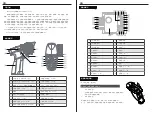
Dial Switch sign
Beginner Mode
ESC Parameter Setting
Beginner mode is designed for people new to the hobby.
In this mode the throttle will be limited to 50 percent, The channel range defaults to 1250~1500~1750 us.
Setup:
To switch between beginner and normal modes press and hold the channel 4 button as the transmitter is turned on.
Note: By default, the system is set to normal mode. The GLED will flash slowly for 3 seconds during power on if the
system is set to beginner mode.
The Dial Switch on the transmitter is used to set ESC parameters, that is, the Dial Switch is located at different
positions and the corresponding parameter values are different.
Setting Method:
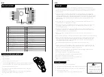
There are three parameters can be set for the ESC, which are "Running mode", "Battery type", "Drag brake", There
are slide switches numbered 1 2 3 4 on the radio panel . The above parameters can be set by dialing down and up.
The specific operation is as follows:
When No. 1 slide switch is on the down, it indicates that the operation mode is set to FWD / REV / BRK.
When No. 1 slide switch is on the up, it indicates that the operation mode is set to FWD/REV.
When No. 2 slide switch is on the down, it indicates that the battery type is set to Lipo.
When No. 2 slide switch is on the up, it indicates that the battery type is set to NiMH.
When No. 3 and No.4 slide switch are on the down, it indicates that the drag brake force is set to 0%.
When No. 3 slide switch is on the down and No.4 slide switch is on the up, it indicates that the drag brake force is set
to 50%.
When No. 3 slide switch is on the up and No.4 slide switch is on the down, it indicates that the drag brake force is set
to 75%.
When No. 3 and No.4 slide switch are on the up, it indicates that the drag brake force is set to 100%
When the transmitter is switched on in normal communication state, keep the channel to be set at the position of the
failsafe setup, and press and hold the BIND button for 3S. The G.LED flashes for 2S, indicating that the setting is
successful. That is, when the receiver cannot receive the signal, it will output the set failsafe value.
Note: The fail-safe function has no default set at the factory and as such must be set manually. If no failsafe setting
has been set, then the receiver will not output anything when signal is lost.
Setup:
EN
Parameter Explanation:
1. Running Mode
FWD/REV/BRK: This mode adopts "double click” reverse mode, that is, when the throttle trigger is pushed from netural
range to the reverse area for the first time, the motor is only braking and will not reverse; when the throttle trigger is
moved back to the netural range and pushed to the reverse area for the second time, it will reverse. This mode is
applicable to general models.
FWD/REV: This mode adopts "one click" reverse mode, that is, when the throttle trigger is pushed from netural range to
the reverse area, the motor immediately generates reverse action, which is generally applied to rock crawler.
Parameter setting method:
When No. 1 slide switch is on the down, it indicates that the operation mode is set to FWD / REV / BRK.
When No. 1 slide switch is on the up, it indicates that the operation mode is set to FWD/REV.
2. Battery Type
There are LiPo and NiMH cells. The low-pressure protection value is different under different types. It can be set according
to the actual use.
Parameter setting method:
When No. 2 slide switch is on the down, it indicates that the battery type is set to Lipo.
When No. 2 slide switch is on the up, it indicates that the battery type is set to NiMH.
3. Drag Brake Force
The drag brake means that when the throttle trigger moves from the forward or reverse area to netural range, it will
produce certain braking force to the motor, the larger the value is, the greater the drag brake force is. Select proper
braking force according to the actual situation.
Parameter setting method:
When No. 3 and No.4 slide switch are on the down, it indicates that the drag brake force is set to 0%.
When No. 3 slide switch is on the down and No.4 slide switch is on the up, it indicates that the drag brake force is set
to 50%.
When No. 3 slide switch is on the up and No.4 slide switch is on the down, it indicates that the drag brake force is set
to 75%.
When No. 3 and No.4 slide switch are on the up, it indicates that the drag brake force is set to 100%.
EN
Setting the Gear Mesh
The gear mesh is the clearance between the pinion and spur gears in your
vehicle. If the motor or gearing components are replaced,check that the
gears are not meshing too tightly as this may cause premature wear.
Charging the Battery
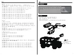
1.Connect the charger to a USB port then connect the battery to the charger.
2.When charging,the Green LED is flash, when charged, the Green LED is stable.
3.Do not let the battery charge unattended!
4. If the battery or charger is hot,disconnect the battery and charger immediately as this may be caused by an internal
short-circuit.
1. Connect the charger's USB port to a power source.
2. Connect the battery to the charger.
15
16


