EN
[1]
[2]
[3]
[12]
[4]
[13]
[5]
[14]
[6]
[15]
[7]
[16]
[8]
[17]
[9]
[18]
[10]
[19]
[11]
[20]
[21]
[22]
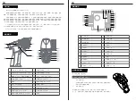
CH1
Antenna
CH3
LED
CH4
Battery line“-”
Left Light port
Battery line“+”
Right Light port
Motor line“M-”
Head Light port
Motor line “M+”
Tail Light port
Power switch line
Ambient Light port
Stickers
Roof Light port
Channel port “S ”
Light port“-”
Channel port“+”
Light port “+”
Channel port“-”
Receiver Overview
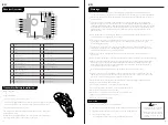
Transmitter Battery Installation
Battery Type:AAA
Battery Installation:
1. Open the battery compartment cover.
2. Insert 4 fully-charged AAA batteries into the compartment. Make sure that the
battery makes good contact with the battery compartment's contacts.
3. Replace battery compartment cover.
Low battery alarm: When the battery is lower than 4.2v, the G.LED on the
panel will flash slowly.
Note: When installing the batteries, be careful to handle the positive and
negative poles. (As shown in the picture on the right)
Power On
Note
Warnings
EN
This vehicle is not intended for those under 14 years of age without proper adult supervision.
It is not a toy!Failure to operate or maintain this vehicle in a safe manner can result in bodily harm.
Replace damaged components with original factory-parts. Pay special attention to the polarity of
all vehicle wiring.
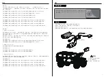
Only use approved 2 cell lithium polymer batteries. Do not over-charge or over dis-charge the
battery as doingso may cause the battery to become a fire hazard. If the battery should become
hot during charging,discontinue charging immediately and disconnect the battery from the charger.
Never leave the battery unattended while charging. If you are unsure of how to charge this battery,
please seek the advice of experienced RC users. Never let children charge the battery without
adult supervision.
The motor will become hot during use. Allow 10-15 minutes between runs for the vehicle to cool
down. Doing so will prolong the life of your vehicle.
Use common sense when selecting the environment to operate your vehicle. Do not operate near
power cables, cellular/radio towers, deep water or unstable terrain. The operator is solely
responsible for their actions.
The product is composed of precision electrical components. It is critical to keep the product
away from moisture and other contaminants. If exposed to a humid environment, make sure the
electronics are fully dried prior to using them again.
Always check the radio range of the vehicle prior to operation in order to prevent radio loss or
interference.
Operate this product within your ability. If the vehicle is dangerous to retrieve, it's never worth the risk.
Always turn on the transmitter before connecting the battery on the model. When turning off the
model, always disconnect the battery first, and then turn off the model, always disconnect the
battery first, and then turn off the transmitter. If this order is reversed, the model may become
uncontrollable and cause serious damage.
Never allow transmitter batteries to run low as it may cause loss of vehicle control.
Plastics on the vehicle are susceptible to damage or deformation due to extreme heat and cold
climate. Do not store the model near any source of heat such as oven or heater. Store the model
indoors, in a climate-controlled, room temperature environment.
Never shorten the receiver antenna; this may affect the transmitting range of the radio system.
Only use specified battery (X4 AAA batteries).
Do not open, disassemble, or attempt to repair the battery.
Do not crush/puncture the battery, or short the external contacts.
Do not expose to excessive heat or liquids.
Do not drop the battery or expose to strong shocks or vibrations.
Always store the battery in a cool, dry place.
Do not use the battery if damaged.
Follow the steps below to turn on the transmitter:
1. Check to make sure that that battery is fully charged and installed correctly.
2. Toggle the switch to the [ON] position. When active the R.LED will be lit.
3. Connect the receiver to power.
• For safety always power on the transmitter before the receiver.
Operate with caution in order
to avoid damage or injury.
Make sure that the throttle is
at its lowest position and the
switches are set to their up
position.
11
12


