C2078
C2079
C2080
C2081
C2082
C2083
C2084
C2085
C2086
C2045
C2046
C2052
C2087
C2051
C1210
C1169
C2049
C2057
C2058
C2088
C2056
C2060
C2089
C2063
C2090
C2065
C2066
C2067
C2068
C2069
C2091
C2071
C2073
C2074
C2075
C2076
C2021
NOTE
EN
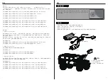
Always charge LiPo batteries on non-flammable, heat-resistant surfaces.
Always use a LiPo-safe bag or container while charging. Do not allow LiPo cells to overheat at any time.Cells which
reach greater than 140 Fahrenheit(60°C) will usually become damaged and will catch fire.
Do not charge the LiPo pack while it is still in the model. Never charge or store battery packs in a vehicle.
Do not discharge LiPo; doing so will damage the battery.
Do not expose LiPo cell to water or moisture at any time.
Do not store battery near open flame or heater.
Do not assemble LiPo cells or pre -assembled packs together with other LiPo cells or packs.
Always store LiPo battery in a secure location away from children.
Always remove the LiPo battery if model is involved in any kind of crash.
Carefully inspect the battery and connectors for even the smallest damage.
CAUTION:Cells may become hot after usage.Allow the pack to cool to room temperature prior to recharging.
Do not allow the electrolyte to get into eyes or on skin.Wash affected areas immediately if they if they come into
contact with electrolyte.Do not alter or modifv connectors or wires of a LiPo battery pack.
Always inspect the condition of the battery before charging and operating.
Do not short circuit the LiPo battery.
Do not have contact with a leaky/damaged battery directly.
Do not charge battery out of recommended temperature range(O°C 45°C).
1.If it is not in use for a long time, unplug and take off the battery to prevent batery leakage
2.Do not open, disassemble, or attempt to repair the battery.
EN
The antenna(s) used for this transmitter must be installed to provide a separation distance of at least 20 cm from all
persons and must not be co-located or operating in conjunction with any other transmitter. End-users and installers
must be provided with antenna installation instructions and transmitter operating conditions for satisfying RF
exposure compliance.
FCC ID: N4ZMG400
This equipment has been tested and found to comply with the limits for a Class B digital device pursuant to part
15 of the FCC rules. These limits are designed to provide reasonable protection against harmful interference in a
residential installation. This equipment generates, uses and can radiate radio frequency energy and, if not installed
and used in accordance with the instructions, may cause harmful interference to radio communications. However,
there is no guarantee that interference will not occur in a particular installation. If this equipment does cause
harmful interference to radio or televison reception, which can be determined by turning the equipment off and on,
the user is encouraged to try to correct the interference by one or more of the following measures:
To assure continued compliance, any changes or modifications not expressly approved by the party responsible for
compliance could void the user's authority to operate this equipment.
This equipment complies with Part 15 of the FCC Rules. Operation is subject to the following two conditions:
(1) This device may not cause harmful interference.
(2) This device must accept any interference received, including interference that may cause undesired operation.
Caution!
The manufacturer is not responsible for any radio or TV interference caused by unauthorized modifications to this
equipment. Such modifications could void the user authority to operate the equipment.
1. The antenna(s) used for this transmitter must be installed to provide a separation distance of at least 20 cm
from all persons and must not be co-lacated or operating in conjunction with any other transmitter.End-users
and installers must be provided with antenna installation instructions and transmitter operating conditions for
satisfying RF exposure compliance.
2. Move all your channels to the desired position.
3. Select [All channels] and then [Yes] in the confirmation box.
• Reorient or relocate the receiving antenna.
• Increase the separation between the equipment and receiver.
• Connect the equipment into an outlet on a circuit different from that to which the receiver is connected.
• Consult the dealer or an experienced radio/TV technician for help.
FIRE HORSE Hood
FIRE HORSE Front and Rear Light Cup Set
FIRE HORSE Hood Mount Set
FIRE HORSE Spare Tire Bracket
FIRE HORSE Rearview Mirror And Wiper
FIRE HORSE Bumper set
FIRE HORSE Lens set
FIRE HORSE Body SHELL
FIRE HORSE handle set
Teraz Tire 19.2 x 13.5 x 56
1:18 Star Style Wheels plastic parts
FMS LIPO Battery 2S LIPO 380mAh
1:18 FIRE HORSE Light set
FMS USB Charger
11221 RECEIVER
HT-TX01 2.4G TRANSMITTER
1:18 050 Motor set
1:18 Plastic Gear set
1:18 Transmission Shaft full set
1:18 FIRE HORSE Screw set
1:18 Drive axle Metal Gear
1:18 M2&M2.5 SCREW NET
1:18 FIRE HORSE Window
1:18 SHOCK PLASTIC PARTS
1:18 FIRE HORSE Connecting Rod
1:18 M4 ALLY BALL
1:18 BALL HEAD
1:18 Steering Hub & Spindle
1:18 FRONT/REAR AXLE parts
1:18 SERVO HORN
1:18 FIRE HORSE MIRROR LENS
1:18 Wheel Hex
1:18 BEARING Set
1:18 Rear Wheel Shaft
1:18 FRONT OUTDRIVE SHAFT
1:18 Gear Box Plastic Parts
1:18 1KG High Torque 3wire Servo
Spare parts list
CE Warning
Appendix 1 FCC Statement
Battery
Motor
ESC&RX
LED
Servo
17
18


