background image


RBTNK­DOC­160609A 

System Elements and Maintenance Manual 

SUMMIT XL mobile platform


3.4 Terminals & Fuses 


Figure 12­ Fuses


At the picture you can see the DIN rail the following fuses:


Fuse F0: 15A (blue) Back panel charge connector & switch S1.


Fuse F1: 40A (orange) Main fuse, connected to battery directly.


Fuse F2: 15A (blue) driver 1.


Fuse F3: 15A (blue) driver 2.


Fuse F4: 15A (blue) driver 3.


Fuse F5: 15A (blue) driver 4.


Fuse F6: 10A (red) 12V DC/DC converter INPUT.


Fuse F7: 7.5A (brown) 12V DC/DC converter OUTPUT (+12V).


Fuse F8: 2A (grey) Back panel 12V output (from DC/DC converter).


Fuse F9: 2A (grey) 5V DC/DC converter OUTPUT (+5V).


16 


Содержание SUMMIT XL

Страница 1: ...SUMMIT XL MOBILE PLATFORM SYSTEM ELEMENTS MAINTENANCE MANUAL RBTNK DOC 160609A Robotnik Automation SLL Spain ...

Страница 2: ...o Laser Range Finder optional 3 Internal Elements 3 1 Embedded PC 3 2 Wireless Router 3 3 DC DC 12VDC 5VDC 3 4 Terminals Fuses 3 4 1 Initial setup of the fuses 3 5 FPU Pixhawk optional 4 Manual Controls 4 1 DualShock controller 5 Battery and Charger 5 1 LiFePO4 battery pack 5 1 1 LiFePO4 Cell 5 1 2 Protection circuit module 5 2 LiFePO4 Smart Charger 6 Communication Diagram 7 Maintenance Summary 8 ...

Страница 3: ...e description of the mechanical component that composes it emphasizing the elements that need a special periodical control and maintenance The location and maintenance of other non mechanical components is also described below Finally a summary of the basic drawings of the vehicle and the main components has been included 2 External Elements The next figures show the main parts of the robot Figure...

Страница 4: ...interior of the robot where some of the control components like the control computer are placed Rear Cover Holds the control panel buttons and the wireless antennas Motor wheels Four motor wheels 250W brushless motor with Hall Effect sensor and a reduction gear box inside the aluminum wheel Battery 24V LiFePO4 battery 8x3 2V 15Ah cells Shocks Four strong shock absorbers optional PTZ cameras protec...

Страница 5: ...ave a much longer life expectancy and a higher efficiency than brushed motors This kind of rubber tire is specially made for Robotnik so contact us if you need to replace them It has a width of 145mm and a diameter of 235mm The motor block diameter is 100mm It is recommended that no weight rests on the wheels for a very long time when stopped to avoid flattening The cable must be kept in good cond...

Страница 6: ...ault one 63 but each driver has its own CAN bus identifier 1 2 3 and 4 DO NOT change them from one motor to another To reduce power consumption if the velocity is zero only the rear wheels brake the front ones are free The computer sends CAN messages to move the robot and they are different from the left side 1 2 and right side 3 4 Driver 1 is the only one with the Can bus resistor installed There...

Страница 7: ...op the robot CAUTION there is no rearm button so the robot will keep moving when the Emergency Stop is released General ON OFF key S1 cuts the power of the whole robot It has a green light indicator CPU POWER blue indicator switch turns on and off the computer 12 VDC intended to power external devices and protected with fuse CHARGER to connect the provided battery charger Two free USB 2 0 ports Et...

Страница 8: ... flip Auto flip 100 preset positions Pan 360 with auto flip 1 8 100 s Tilt 180 1 8 100 s 12x optical zoom 10x digital zoom total 120x zoom Limited guard tour Control queue Video Resolution 1280x720 to 320x180 Compression H 264 MPEG 4 Part 10 AVC Baseline Main and High Profiles Motion JPEG Connectors RJ45 10BASE T 100BASE TX PoE Multi connector cable not included for AC DC power 4 configurable alar...

Страница 9: ...Finder optional The robot can be equipped with several models with our specific adaptors Below you can see the laser range finders usually mounted URG 04LX UG01 Light weight 160g Wide Angle 240º Range 5600mm Accuracy 30mm Distance and angle data output with high angular resolution 0 352 Low power consumption 2 5W UTM 30LX Outdoor Environment Light weight 370g Wide Angle 270 Long Detection range 30...

Страница 10: ...ystem Elements and Maintenance Manual SUMMIT XL mobile platform 3 Internal Elements The following figure shows other non mechanical components to be in consideration for maintenance tasks Figure 7 Summit XL inside view 10 ...

Страница 11: ...limeters 0 79 inches x 170 18 millimeters 6 7 inches x 170 18 millimeters 6 7 inches Processor Chipset Intel Bay Trail J1900 Processor with integrated graphics Remark Compatible with J1800 and J2900 Memory Support for dual channel DDR3L 1333 1600 runs at 1333 MHz SO DIMMs Support for up to 8 GB of system memory on a single SO DIMM or 4 GB each by 2 SO DIMM 204 pin DDR3L SO DIMM 2 Graphics Integrat...

Страница 12: ...ard slot 1 Peripheral Interfaces USB 2 0 front panel ports 5 USB 3 0 back panel connectors blue 2 USB 2 0 high current fast charging ports Yellow 2 SATA 3 0 Gb s 2 SATA 3 0 Gb s port multiplexed with an mSATA port routed to the PCI Express Full Half Mini Card slot 1 Legacy I O Legacy I O Controller NCT6683D that provides Hardware management support Serial ports onboard headers 2 Parallel port via ...

Страница 13: ... problem can be due to the accumulation of dust in the internal components so it acts as thermal insulator The heat generated by the components cannot be well dissipated because it is trapped in the dust layer The oil and grease particles contained in the environmental air mix with the dust creating thus a big insulation layer that reflexes the heat to other components This effect causes a reducti...

Страница 14: ...ed with smaller 5dB antennas Technical Specification Wireless Data Transfer Rate 802 11n 300Mbps Supports router access point range extender modes Port triggering for special applications DDNS and SIP Guest network Virtual server and DMZ hosting MAC IP filter and URL blocking Static routing UPnP architecture VPN pass through IPSec PPTP Wi Fi schedule control 14 ...

Страница 15: ... DC 12VDC 5VDC There is a 150W 12V DC DC to provide a stable power supply for the electronic elements PC Axis camera external power Figure 10 12V DC DC There is a small 5V DC DC which powers the AGVCTRL V2 optional and the motor drivers It is located under the DIN rail Figure 11 5V DC DC 15 ...

Страница 16: ...ack panel charge connector switch S1 Fuse F1 40A orange Main fuse connected to battery directly Fuse F2 15A blue driver 1 Fuse F3 15A blue driver 2 Fuse F4 15A blue driver 3 Fuse F5 15A blue driver 4 Fuse F6 10A red 12V DC DC converter INPUT Fuse F7 7 5A brown 12V DC DC converter OUTPUT 12V Fuse F8 2A grey Back panel 12V output from DC DC converter Fuse F9 2A grey 5V DC DC converter OUTPUT 5V 16 ...

Страница 17: ...y and back panel in the fuse holder before turning on the robot Important Electrical damage danger Check the power ON OFF is in OFF position before plug any fuse in the fuse holder Figure 13 Power button in OFF position Insert 15A fuse in the fuse holder labelled with F0 Insert 40A fuse in the fuse holder labelled with F1 See electric drawings manual for detailed information 17 ...

Страница 18: ...ride 6 auxiliary high power compatible Abundant connectivity options for additional peripherals UART I2C CAN Integrated backup system for in flight recovery and manual override with dedicated processor and stand alone power supply fixed wing use Backup system integrates mixing providing consistent autopilot and manual override mixing modes fixed wing use Redundant power supply inputs and automatic...

Страница 19: ... in 6 GND 1 FTDI GND black Table 4 FTDI_USB to UART pinout More info in https pixhawk org modules pixhawk 4 Manual Controls The gamepad functions are fully explained in the System Start up Manual 4 1 DualShock controller The Gamepad used for the manual movements of the robot SUMMIT XL is a Bluetooth Joystick The receiver is located inside the robot and connected to one USB port of the computer The...

Страница 20: ...es For charging the batteries there is a connector at the back panel of the robot where the charger can be connected It is a direct connection so the general ON OFF switch doesn t affect the charging It is possible to charge the robot and keep working at the same time without any problem Full charging time is around 45 60 minutes for the supplied charger Do not use other chargers without checking ...

Страница 21: ...id escape currents Check the wear out of the battery wires to prevent short circuits The battery can be separated from the robot by taking out the bottom aluminum protection and unplugging the power supply connector red and blue wires and the charge connector yellow wire It is recommended to have the robot upside down to do this process The battery weight is 4kg and will fall when the screws are r...

Страница 22: ...000mAh Normal voltage 3 2V Inter impedance 8mOhms Maximum continuous Discharge Current 10C 150A Charging Temperature 10 45ºC 14 113º F Discharging Temperature 20 60ºC 14 140ºF Cycle Performance 2000 80 of initial capacity at 1C rate Standard Charging current 1C 15A Max 5C 75A Weight 500g 5 1 2 Protection circuit module Figure 19 Protection circuit module 22 ...

Страница 23: ...load or charge Normal working current A 30 Over current protection A 60 Internal resistance m ohm 30 Charging balancing current mA 60 Charging balancing voltage V 3 63 0 03 Over charge postpone time mS 1 2 Over discharge postpone time mS 144 Temperature protection ºC 65ºC option Temperature characteristic 1 0mv ºC Working temperature ºC 10 60 Storage temperature ºC 30 85 Power loss uA 400 Vn 3 2v ...

Страница 24: ...tery pack IMPORTANT CHECK POWER SELECTION BEFORE PLUGGING IT Specifications INPUT o 115 230VAC Worldwide power input support by Adjustable switch o Input frequency 50 60Hz CHARGE o Charging current 12A o Protection Short circuit protection Over voltage protection Over current protection Reverse polarity protection o The charger will cut off automatically if battery is fully charged OUTPUTS o 29 2V...

Страница 25: ...re 10ºC 70ºC Caution The charger is designed for indoor use only The charger should be placed horizontally and operate in well ventilated condition avoid humidity and keep it away from inflammable explosive material The aluminum case is a heat sink do not cover it Do not disassemble the charger due to high voltage inside Figure 21 LiFePo4 Smart Charger Front view Figure 22 LiFePo4 Smart Charger Re...

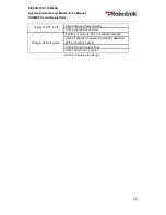
Страница 26: ...r LED1 is off Check charger Power Switch Check charger Input Fuse Charger LED2 is green If battery is close to 29 2V is already charged Check if charger connector is properly attached at the robot back panel Check charger Output Fuse Check Summit XL Fuse F0 Table 6 Charging trouble tips 26 ...

Страница 27: ... platform 6 Communication Diagram The following figure shows the communication diagram existing inside the robot The functionality of the system can be further extended by using the free Ethernet ports and free USB port inside and outside Figure 23 Communications diagram 27 ...

Страница 28: ...month Observations Screws Check they are not loosen Tires Visual control of the wear rate Replace when needed Outer wires Visual control of the wear rate If wear appears protect them with Shrink tube Vulcan tape or similar Bearings Control state If any damage appears it is recommended its replacement by a new one Battery Control Batteries Voltage don t let the batteries get fully discharged Check ...

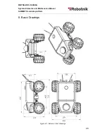
Страница 29: ...RBTNK DOC 160609A System Elements and Maintenance Manual SUMMIT XL mobile platform 8 Basic Drawings Figure 24 External robot drawings 29 ...

Отзывы: