7
EN
G
LI
SH
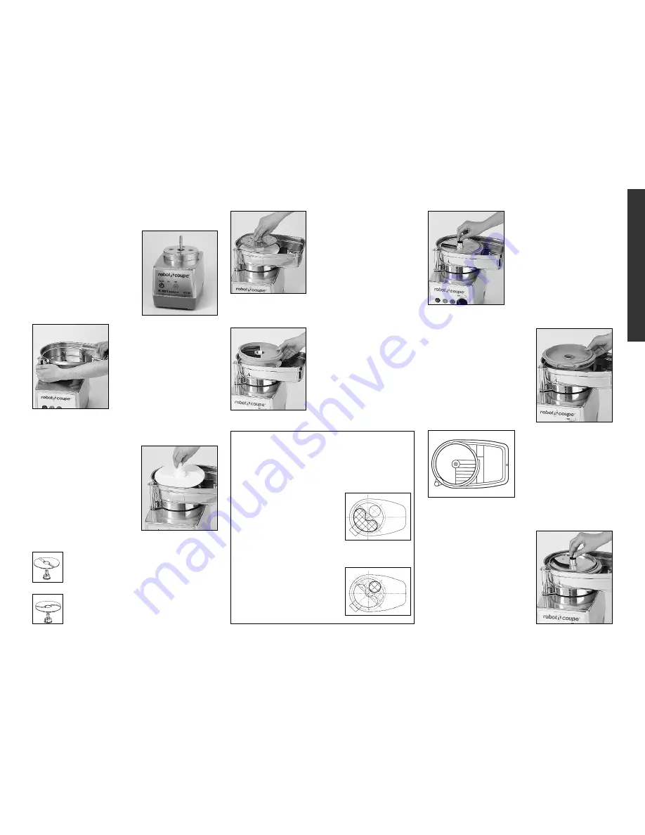
• VEGETABLE PREPARATION ATTACHMENT
1) The vegetable prepara-
tion attachment consists of
two detachable parts : the
continuous feed attachment
and the continuous feed
lead.
Place the matching slicing
plate onto the discharge
plate. You may need to rotate
the plate a bit until it drops
into place on the discharge
plate. Tighten the plate-
securing knob by turning it
clockwise.
Only For the R 402 Series A and R 402 V. Series A
models:
If you have chosen the
dicing combination:
i.e. a
grid and a specific slicing
disc.
8 mm, 10 mm and 12 mm
discs only can be fitted with
a dicing grid.
Position the dicing grid in
the vegetable preparation
bowl.
4) Place the cutting plate
of your choice onto the
discharge plate. It may be
necessar y to rotate the
cutting plate until it engages
and drops fully onto the
discharge plate.
SIDE A
: Straight ejection ribs facing
upwards, for any vegetables or citrus fruit
which require careful handling (tomatoes,
mushrooms...).
SIDE B
: Cur ved ejection ribs facing
upwards in all other cases.
3) Place the white discharge
plate onto the motor shaft. It
should fall into place just off
the bottom of the continuous
feed attachment.
Depending on type of use
(Side A or B), the discharge
plate may be removed from
the hub and flipped over.
2) With the motor base
facing you, fit the conti-
nuous feed attachment onto
the motor base; the exit
chute should be on your
right.
Turn the attachment back to
the right (counterclockwise)
until it comes to a stop loc-
ked in place on the motor base tabs.
Next fit the appropriate
slicing disc and screw the
slicer on the motor shaft
with the butterfly nut.
• INSTALLING THE DICING GRID:
The grid must be positioned according to the fee-
ding hopper used.
Failure to do so, can lead to
jamming and motor damage.
• Position 1 :
Using the
large hopper.
In this case, the dicing grid
should be positioned so that its
blades are vertically aligned
with the hopper. (You must be
able to see the grid blades
when looking into the hopper.)
• Position 2 :
Using the
cylindrical hopper.
In this case, the grid must be
positioned so that the blades
are vertically aligned with the
tube. (You must be able to see
the grid blades when looking
into the tube.)
INSTALLING THE FRENCH FRY GRID :
Specially designed slicing
plates and matching grids
have been developed for
making French fries. Two
sizes are available: 8x8
and 10x10.
With the discharge plate
in place on the motor
shaft, place the French fry
grid into the continuous
feed attachment with the
vertical blades aligned
toward the discharge
chute.
If the grid is not in the correct position,
jamming and motor damage may occur.
Содержание R 401 Series A
Страница 11: ...27 TECHNICAL DATA DATOS TECNICOS DONNÉES TECHNIQUES ...
Страница 12: ...28 ...
Страница 13: ...29 ...
Страница 14: ...30 ...
Страница 15: ...31 ...
Страница 16: ...32 ...
Страница 17: ...33 ...
Страница 18: ...34 ...
Страница 19: ...35 ...
Страница 20: ...36 ...
Страница 21: ...37 ...


