ROBERTS GORDON
®
CORAYVAC
®
M
ODULATING
H
EATING
C
ONTROL
C
ONTROLLER
I
NSTALLATION
M
ANUAL
60
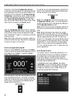
Continue to scroll down
Configuration-Service
screen and set each selection to the appropriate set-
ting (depending on what type of heat system(s) are
connected to the controller). The
'External Design
Temperature'
should reference the coldest possible
outside air temperature during the heating season,
The
"Internal Design Temperature"
should refer-
ence the warmest desired space temperature. Press
the home icon to return to the
Home
screen.
Home Icon
After the
Configuration-Service
screen is adjusted,
the
Home
screen will show zone-to-pump associated
wiring. Yellow and blue lines indicate which pump
each CORAYVAC
®
system is connected to within the
controller's logic.
Note:
Ensure the hardwired connections match the
connection within the logic. Repeat this configuration
for each controller on the network.
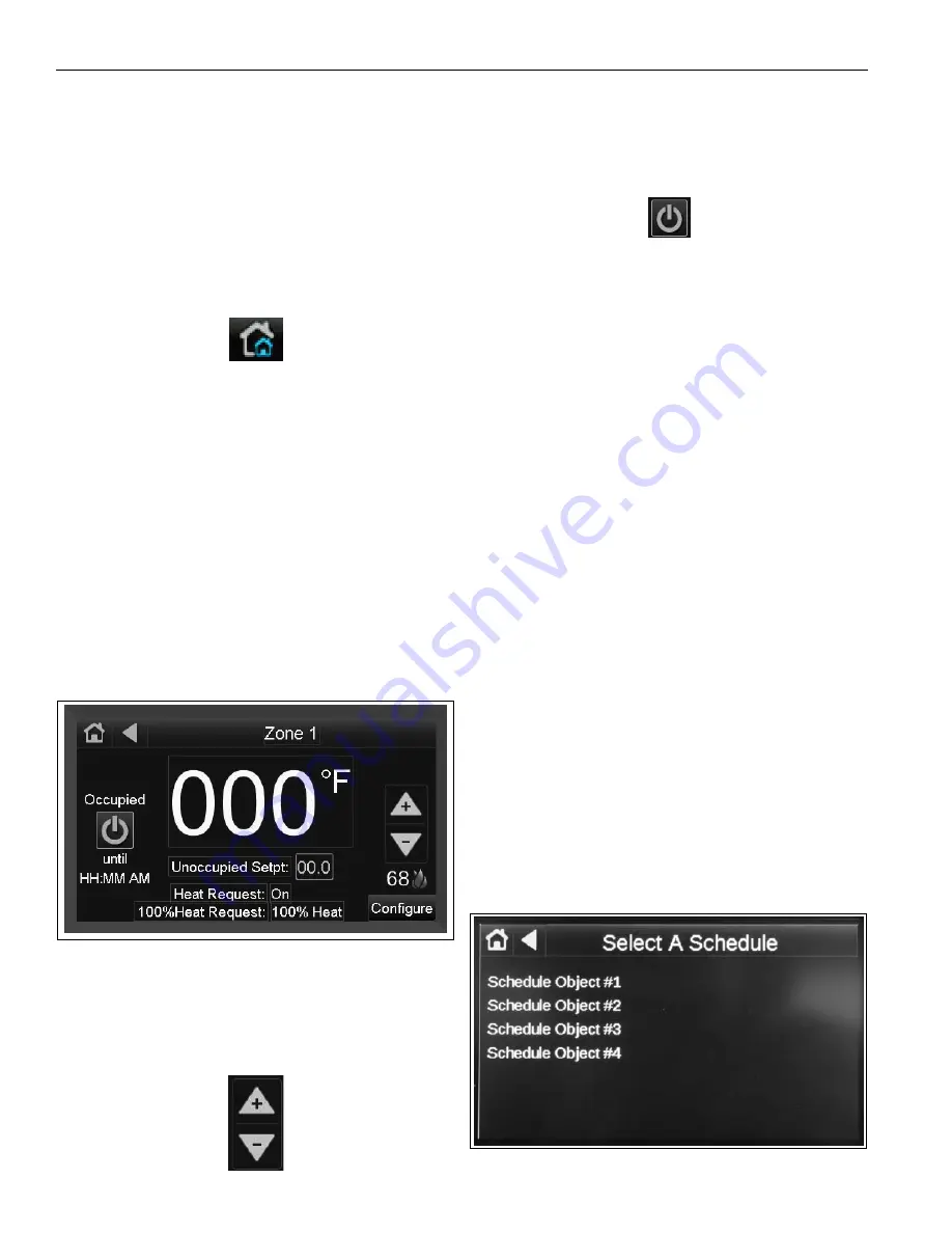
8.4 Zone Temperature Setpoints
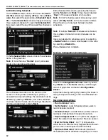
Press any of the
'Zone #'s'
displayed on the
Home
screen to access the temperature adjustments for the
associated zone. If
'Zone 1'
is selected,
'Zone 1'
screen will be accessed.
From this screen, users can make adjustments to the
zone temperature setpoint, or override a schedule.
Adjust the occupied setpoint by pressing the up and
down arrows to the desired zone temperature dis-
played next to the flame icon.
Arrow Buttons
To override an unoccupied temperature, select the on
button icon to select the desired space temperature
and the duration of the override.
On Button Icon
Note:
The
<Configure>
icon will bring users to the
Configuration-Zones
screen. It is recommended to
create all schedules prior to adjusting the settings in
the
Configuration-Zones
screen.
Note:
Allow a few seconds after adjusting setpoint for
information to process before navigating away from
page.
Note:
Setpoint displayed also reflects any adjust-
ments made at the zone sensor. This is the "Effective
Setpoint". For example: If the setpoint is at 68 °F and
the user adjusts the setpoint to 70 °F at the zone
sensor, 70 °F will appear on the zone screen. Adjust-
ments made at the touchscreen will be from the base
setpoint (68 °F). If user, then turns up the tempera-
ture 2 F° more, it will show the adjustment from 68
F°- 70 F°, and then jump to 72 F° to reflect the zone
sensor adjustment.
8.5 Schedule Creation
To maximize comfort and system performance, it is
recommended to program your heating schedule in
accordance with your occupied and unoccupied
zones and schedule. For best results, keep your
night setback temperature within 5 °F to 8 °F of your
occupied setpoint temperature.
In the
Home
screen select
<Menu>
then select
<Schedules>
. A list of schedule objects numbered 1
through 4 will appear. The schedule object number
corresponds with each zone number. Each zone
should be programmed individually.
Содержание CORAYVAC
Страница 2: ......
Страница 4: ......
Страница 69: ...SECTION 8 PROGRAMMING AND TROUBLESHOOTING THE SYSTEM 65 THIS PAGE LEFT INTENTIONALLY BLANK ...
Страница 71: ...SECTION 9 TROUBLESHOOTING 67 FIGURE 26 Vacuum pump does not turn on ...
Страница 73: ...SECTION 9 TROUBLESHOOTING 69 FIGURE 28 VFD showing a fault sign FIGURE 29 VFD input power issue ...
Страница 75: ...SECTION 9 TROUBLESHOOTING 71 FIGURE 31 Burner troubleshooting in manual mode ...
Страница 77: ...SECTION 9 TROUBLESHOOTING 73 After 45 second prepurge burners do not light continued ...
Страница 79: ...SECTION 9 TROUBLESHOOTING 75 FIGURE 34 APS does not close within 60 seconds after VFD receives run command ...
Страница 81: ...SECTION 9 TROUBLESHOOTING 77 FIGURE 36 Air Pressure Switch alarm ...
Страница 83: ...SECTION 9 TROUBLESHOOTING 79 FIGURE 38 Repeater troubleshooting ...
Страница 85: ...SECTION 9 TROUBLESHOOTING 81 BACnet MS TP troubleshooting continued ...
Страница 109: ...SECTION 13 TOUCHSCREEN TREE 105 Touchscreen Tree Overview continued ...
Страница 111: ...SECTION 13 TOUCHSCREEN TREE 107 FIGURE 47 Maintenance Unit FIGURE 48 Alarms ...
Страница 113: ...SECTION 13 TOUCHSCREEN TREE 109 FIGURE 51 Configuration Zones FIGURE 52 Configuration Unit ...
Страница 115: ...SECTION 13 TOUCHSCREEN TREE 111 FIGURE 55 Touchscreen System FIGURE 56 Touchscreen Setup ...
Страница 118: ...ROBERTS GORDON CORAYVAC MODULATING HEATING CONTROL CONTROLLER INSTALLATION MANUAL 114 ...
Страница 119: ...SECTION 14 THE ROBERTS GORDON CORAYVAC COMPLETE MODULATING HEATING CONTROL LIMITED WARRANTY 115 ...


