background image

15

Betriebsanleitung, Operating instructions instructions, Notice d’utilisation

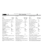
1:10 On road-Chassis

Starten und Einlaufhinweise

- Wir empfehlen, die ersten Fahrversuche ohne

Karosserie durchzuführen, bis der Motor eingestellt ist.

- Auf festen Sitz des Luftfilters achten. Staub, der in den

Vergaser gelangt, beschädigt den Motor.
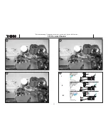
Bild 21

- Modell auftanken. 

Bilder 22 und 23

- Durch mehrmaliges Drücken auf die Pumpmechanik

des Tanks wird Kraftstoff zum Vergaser gefördert.
Solange pumpen bis Sie erkennen können, dass der
Kraftstoff durch die Schlauchleitung in den Vergaser
eintritt - siehe Pfeil.

Bild 24

- Glühkerzenstecker auf die Glühkerze aufsetzen. Den

Motor mit dem Seilzugstarter anlassen. Der Gashebel
muss sich in Leerlaufstellung befinden. Seilzugstarter
immer nur zu etwa 2/3 der Seillänge herausziehen. 

- Wenn der Motor nach vier bis fünf Startversuchen nicht

anspringt oder sich nur sehr schwer betätigen lässt,
führen Sie folgende Schritte durch:

- Möglicherweise befindet sich zuviel Kraftstoff im

Brennraum. In diesem Fall die Glühkerze herausschrau-
ben  (Steckschlüssel SW8) und durch mehrfaches
Starten den überschüssigen Kraftstoff ausblasen. 

- Achten Sie darauf, daß Sie sich nicht mit Gesicht oder

Händen über der Kerzenöffnung befinden.

- Startvorgang wiederholen.

Starting the motor, notes on running-in

- We recommend that you carry out the first few trial runs

without the bodywork fitted; at least until you have
established the final settings for the motor.

- Ensure that the air filter is firmly attached. Any dust

which gets inside the carburettor will damage the
motor.

Fig. 21

- Fill the fueltank.

Figs. 22 and 23

- Press the pump mechanism on the fueltank repeatedly

to force fuel through to the carburettor. Continue pum-
ping until you see fuel entering the carburettor through
the fuel line -

see arrow.

Fig. 24

- Push the glow driver onto the glowplug. Check that the

throttle lever is at the idle position, then start the motor
by pulling the pull-cord starter. Never pull out the star-
ter cord more than about 2/3 of its full length.

- If the motor does not start after four or five attempts, or

is very difficult to turn over, carry out the following pro-
cedure:

- There may be too much fuel in the combustion cham-

ber. Check this by unscrewing the glowplug complete-
ly (8 mm A/F box spanner) and pull the starter cord
several times to blow out the excess fuel.

- Keep your face and hands away from the glowplug hole

while you are doing this.

- Repeat the starting procedure.

Démarrage et conseils de rodage

- Nous recommandons d’effectuer les premiers essais

sans carrosserie jusqu’à ce que le moteur soit parfaite-
ment réglé.

- Contrôler l’assise du filtre à air. Si de la poussière entre

dans le carburateur, elle risque de le détériorer.

Fig. 21

- Faire le plein du réservoir du modèle. 

Figures 22 et 23

- En appuyant plusieurs fois sur la mécanique de pom-

page du réservoir, amener le carburant jusqu’au réser-
voir. Pomper jusqu’à ce qu’il soit possible de constater
le passage du carburant dans le flexible d’alimentation
jusqu’au carburateur - Cf. flèche.

Fig. 24

- Installer le soquet à bougie sur la bougie. Démarrer le

moteur à l’aide du démarreur à cordelette. Le manche
des gaz doit se trouver au ralenti. Ne tirer le démarreur
à cordelette chaque fois que des 2/3 de la cordelette
environ. 

- Si le moteur ne démarre pas après quatre ou cinq

essais de démarrage, ou si le moteur est difficile à faire
tourner, effectuer les opérations suivantes dans la
séquence décrite :

- il est possible qu’il y ait trop de carburant dans la cham-

bre de combustion. Dans ce cas, dévisser la bougie (clé
à tube de 8 surplat) et en actionnant plusieurs fois le
démarreur, éjecter l’excédent de carburant. 

- Veiller à ne pas approcher le visage ou les mains de

l’ouverture de la bougie pendant cette manœuvre.

- Reprendre la procédure de démarrage.

Содержание S3003

Страница 1: ...1 10 On road Chassis Betriebsanleitung Operating instructions Notice d utilisation...

Страница 2: ...ite thread lock fluid 5074 Air filter oil 70081000 Tank filler bottle 7565 Roktan S 10 glow fuel 5315 Polycarbonate paints To choice Small pointed nose pliers Cross point screwdriver Allen key size 1...

Страница 3: ...Betriebsanleitung Operating instructions instructions Notice d utilisation 1 10 On road Chassis 4 1 2 3 4 G 50 mm...

Страница 4: ...the moun ting lugs of both servos Screw the front servo mount to the steering servo Note the kit is supplied with servo output arms with different spline patterns The arms for Futaba servos are marke...

Страница 5: ...5 6 7 8 6 Betriebsanleitung Operating instructions instructions Notice d utilisation 1 10 On road Chassis...

Страница 6: ...gular hole in the cover Fig 7 installing the throttle servo Place the throttle servo in the opening next to the RC box and secure it with four self tapping screws Fig 8 throttle brake pushrod Cut away...

Страница 7: ...Betriebsanleitung Operating instructions instructions Notice d utilisation 1 10 On road Chassis 12 9 8 10 11...

Страница 8: ...king care to main tain correct polarity Connect the battery box to the switch harness Locate the flexible wire aerial attached to the receiver and thread it out through the hole in the lid Fig 12 inst...

Страница 9: ...Betriebsanleitung Operating instructions instructions Notice d utilisation 1 10 On road Chassis 13 10 14 15 16...

Страница 10: ...n the reverse order i e receiver first Fig 16 steering Check the steering when you turn the steering wheel to the right left the front wheels must also turn to the right left If this is not the case o...

Страница 11: ...Betriebsanleitung Operating instructions instructions Notice d utilisation 1 10 On road Chassis 17 18 12 19 20 I II III...

Страница 12: ...djust the position of the collets on the throttle pushrod until this is the case Fig 19 Move the lever fully forward to the Brake position This action compresses the spring on the throttle pus hrod Th...

Страница 13: ...Betriebsanleitung Operating instructions instructions Notice d utilisation 1 10 On road Chassis 21 22 14 23 24...

Страница 14: ...e see arrow Fig 24 Push the glow driver onto the glowplug Check that the throttle lever is at the idle position then start the motor by pulling the pull cord starter Never pull out the star ter cord m...

Страница 15: ...Betriebsanleitung Operating instructions instructions Notice d utilisation 1 10 On road Chassis 16 27 28 26 25 L HD...

Страница 16: ...rom the silencer A rich mixture is achieved by unscrewing the main needle valve HD in small increments The new motor has to be run in for about five comple te tankfuls of fuel before it is capable of...

Страница 17: ...Betriebsanleitung Operating instructions instructions Notice d utilisation 1 10 On road Chassis 18 30 29 31...

Страница 18: ...t alters the model s ground clearance not the stiffness of the suspension Ground clearance only needs to be adjusted to suit the surface quality of the track you are using It should always be set to t...

Страница 19: ...Betriebsanleitung Operating instructions instructions Notice d utilisation 1 10 On road Chassis 20 32 33 1 2 3...

Страница 20: ...act with the ground model as supplied Shortening the upper adju stable transverse arm applies negative camber to the axle This results in higher traction through turns as the car leans into the bend b...

Страница 21: ...3X12 3X30 TP 3X30 TP E2 5 E2 5 4MM 3X35TP 3X35TP 3X12TP 3X12TP 3X12TP 3X12TP M3X12 M3X12 E4 0 M3X3 SET M3X3 SET 3X12TP 3X12TP 3X12TP 3X12TP 3X12TP 3X12TP E2 0 20170087 20170087 20170088 20170088 20170...

Страница 22: ...E DU MOTEUR 2 PIECES 20170020 SCHALLDAEMPFERDICHTUNG EXHAUST GASKET JOINT DU SILENCIEUX 20170021 ZWEIBACKENKUPPLUNG MIT FEDER 2 SHOES CLUTCH W SPRING EMBRAYAGE A DEUX MASSELOTTES AVEC RESSORT 20170022...

Страница 23: ...RALWELLENMITNEHMER 2 ST CUP JOINT 12x21 2 ENTRAINEUR DE L ARBRE CENTRAL 2 PIECES 20170063 UNTERLEGSSCHEIBE 5X12 2 ST 5x12 WASHERS 2 RONDELLES ENTRETOISES 5X12 2 PIECES 20170064 RX BOX SET BATT RECEIVE...

Страница 24: ...NNECTING ROD GUDGEON PIN BIELLE AXE DE PISTON 20171013 KURBELWELLE CRANKSHAFT VILEBREQUIN 20171014 KONUS DRIVE COPPER WASHER C NE 20171015 SCHWUNGRADMITNEHMER DRIVE GEAR ENTRAINEUR DE VOLANT 20171016...

Страница 25: ...70004 20170005 20170006 20170007 20170008 20170009 20170010 20170011 20170012 20170013 20170014 20170015 20170016 20170017 20170018 20170019 20170020 20170021 20170022 20170023 7504 20170025 20170026...

Страница 26: ...50 20170051 20170052 20170053 20170054 20170055 20170056 20170057 20170058 20170059 20170060 20170061 20170062 20170063 20170064 20170065 20170066 20170067 20170068 20170069 20170070 20170071 20170072...

Страница 27: ...171006 20171007 20171029 20171018 20171031 20171009 20171030 20171002 20171010 20171001 20171035 20171034 20171033 20171017 20171017 Betriebsanleitung Operating instructions instructions Notice d util...

Страница 28: ...tung 1 Set 90 exhaust manifold No 20172011 incl screws and gasket 1 set Coude collecteur 90 r f 20172011 avec vis et joint 1 kit 2 Ganggetriebe No 20172000 42 46 Z hne 1 Set 2 speed gearbox No 2017200...

Страница 29: ...d eloxided 1 set Porte frein en alu r f 20172014 aluminium frais sur machines commande num rique anodis 1 kit Alu Querlenkerhalter vorne No 20172013 Aluminium CNC gefr st eloxiert 1 St ck Aluminium fr...

Страница 30: ...ium CNC gefr st eloxiert 2 St ck Aluminium rear stub axle No 20172020 Aluminium CNC machined eloxided pack of 2 Fus e d essieu en alu arri re r f 20172020 aluminium frais sur machines commande num riq...

Страница 31: ...er robbe Modellsport GmbH Co KG Errors and omissions excepted Modifications reserved Copyright robbe Modellsport 2003 Copying and re printing in whole or in part only with prior written approval of ro...

Отзывы: