13
Betriebsanleitung, Operating instructions instructions, Notice d’utilisation
1:10 On road-Chassis
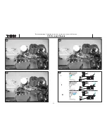
Bild 17, Vergaser und Bremse
- Den Luftfilter abnehmen, um die Stellung des
Drosselkükens im Vergaser prüfen zu können.
- Gas - Bremshebel in das Sendergehäuse drücken.
(“Vollgasstellung”). Das Drosselküken im Vergaser
muß ganz öffnen und die Bremse darf nicht greifen.
- Wenn das Drosselküken geschlossen bleibt und die
Bremse greift, Servo-Reverse Schalter an der Sender-
Rückseite betätigen.
Bild 18
- In Leerlaufstellung (Mittelstellung) ist der Vergaser bis
auf einen schmalen Spalt (ca. 0,5 mm) komplett
geschlossen und die Bremse greift nicht!
- Stellringe auf dem Gasgestänge, falls erforderlich, ent-
sprechend verschieben.
Bild 19
- Den Hebel ganz nach vorn in Stellung „Bremsen“ fah-
ren. Die Feder auf dem Gasgestänge wird dabei zusam-
mengedrückt. Das Drosselküken im Vergaser darf nur
so weit schließen, daß noch eine schmale Öffnung zu
erkennen ist (ca. 0,5 mm). Gleichzeitig muss der
Bremshebel und der daran befestigte Bremsexenter die
Backen der Bremse so weit betätigen, daß die Bremse
voll greift. Die richtige Bremskraft kann erst im
Fahrversuch ermittelt werden.
Bild 20
- Die Stellungen von Drosselküken und Bremse
- Bild I:
Vollgas, Bremse gelöst
- Bild II:
Leerlauf, Bremse glöst
- Bild III:
Leerlauf, Bremse greift
- Luftfilter wieder aufsetzen und mit dem kleinen
Kabelbinder sichern.
Fig. 17, carburettor and brake
- Remove the air filter so that you can check the position
of the throttle barrel in the carburettor.
- Push the throttle / brake lever into the transmitter case
(„full-throttle position“). The throttle barrel in the carbu-
rettor should now open fully, and the brake should not
engage.
- If the throttle barrel remains closed and the brake enga-
ges, operate the servo reverse switch on the rear face
of the transmitter.
Fig. 18
- At the idle position (centre) the carburettor should be
completely closed apart from a narrow slit (approx. 0.5
mm), and the brake should not engage.
- If necessary adjust the position of the collets on the
throttle pushrod until this is the case.
Fig. 19
- Move the lever fully forward to the „Brake“ position.
This action compresses the spring on the throttle pus-
hrod. The throttle barrel in the carburettor should now
close to the point where only a narrow slit is visible
(approx. 0.5 mm). At the same time the brake lever and
the brake eccentric attached to it should move the
brake shoes until the brake engages fully. The correct
braking force can only be found during trial-runs.
Fig. 20
- Throttle barrel and brake positions
- Fig. I: Full throttle, brake disengaged
- Fig. II: Idle, brake disengaged
- Fig. III:Idle, brake engaged
- Fit the air filter again and tighten the small cable tie
to secure it.
Fig. 17, Carburateur et frein
- La tringle des gaz et du frein est préréglée à l’usine.
- Retirer le filtre à air pour pouvoir contrôler la position du
boisseau dans le carburateur.
- Lorsque vous poussez le manche des gaz/frein dans le
boîtier de l’émetteur (”position plein gaz”), le boisseau
dans le carburateur doit être entièrement ouvert et le
frein ne doit pas mordre.
- Si le boisseau reste fermé et que le frein mord,
actionner le commutateur d’inversion de la course du
servo sur la partie arrière de l’émetteur.
Fig. 18
- En position ralenti (position médiane) le carburateur est
pratiquement fermé, il ne subsiste qu’une petite ouver-
ture (approximativement 0,5 mm) et le frein ne mord
pas!
- Si nécessaire, décaler las bagues d’arrêt en consé-
quence sur la tringle des gaz.
Fig. 19
- Amener le manche complètement vers l’avant en posi-
tion “freinage”. Le ressort sur la tringle est alors com-
plètement comprimé. Le boisseau doit pratiquement
être fermé dans le carburateur, il ne doit subsister qu’u-
ne petite fente (approximativement 0,5 mm).
Simultanément, le palonnier de frein et l’excentrique
solidaire doivent actionner les mâchoires du frein de
manière que le frein agisse. L’effort de freinage sera
déterminé après les premiers essais du modèle.
Fig. 20
- Les positions du boisseau et du frein
- Fig. I:
plein gaz, frein desserré
- Fig. II:
ralenti, frein desserré
- Fig. III:ralenti, le frein mord
- Remettre le filtre à air en place et le fixer avec une
petite ligature de câble.
Содержание S3003
Страница 1: ...1 10 On road Chassis Betriebsanleitung Operating instructions Notice d utilisation...
Страница 13: ...Betriebsanleitung Operating instructions instructions Notice d utilisation 1 10 On road Chassis 21 22 14 23 24...
Страница 17: ...Betriebsanleitung Operating instructions instructions Notice d utilisation 1 10 On road Chassis 18 30 29 31...
Страница 19: ...Betriebsanleitung Operating instructions instructions Notice d utilisation 1 10 On road Chassis 20 32 33 1 2 3...


