


30
As a policy of continual improvement, RMF reserves the right to alter the specification without prior notice.
201.028 REV 1
Date of Issue: 18 June 2018
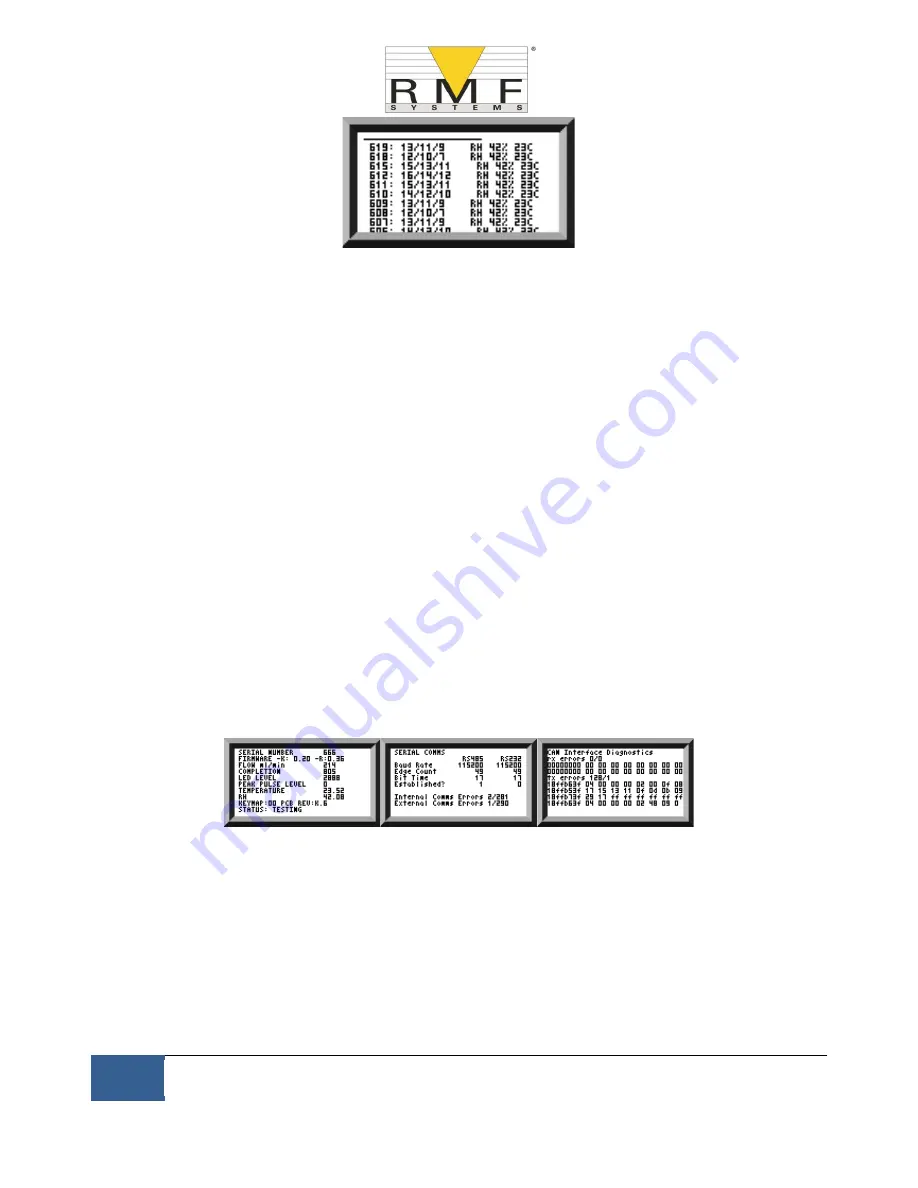
Figure 6.14 History Screen
The progress of a test is denoted by the horizontal line; it grows from left to right as the test progresses. When it
reaches the right hand side a new result is generated.
6.2.2.2.2 Diagnostics Display
Press
◄ or
►
to show the diagnostics displays (used when diagnosing problems) shown in figure 6.15. Then
switch between the diagnostics screens using the
▲
and
▼
buttons.
Completion shows a number from 0 to 1000, indicating the test progress.
FLOW ml/min provides an approximate indication of flow rate, updated after each test.
NOTE: This is not a calibrated flow meter and is for indicative purposes only.
This can be helpful when installing the unit or checking operation, to ensure that the flow rate is within the limits
of the unit. The other items are mainly of use to assist in support when reporting problems.
The STATUS line shows the current state of the unit. Any errors such as LOW FLOW will also appear here
(corresponding to the front panel LED fault codes).
The second screen shows diagnostics relating to Modbus serial communications traffic. External Comms Errors
are those between a connected PC and the CMS. Internal Comms Errors are internal to the unit, showing
communications between the CMS keyboard/display circuit board and the sensor itself.
The third screen shows diagnostics related to CAN bus communications.
General
Modbus
CAN Bus
Figure 6.15 Diagnostics Screens
6.2.3 CMS removal and Product Maintenance
When removing the CMS from the system ensure the system pressure is shut off from the CMS.
Blockages
−
If a suspected blockage occurs then flush system fluid in the reverse direction of the CMS.
−
If this doesn’t solve the problem then try using Iso
-Propyl Alcohol or Petroleum Ether, flushing in the
standard and reverse flow direction.
Содержание CMS 2
Страница 1: ...User Manual CMS2...


