background image


Bump Testing a GX-2009 • 27

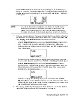
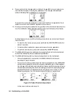
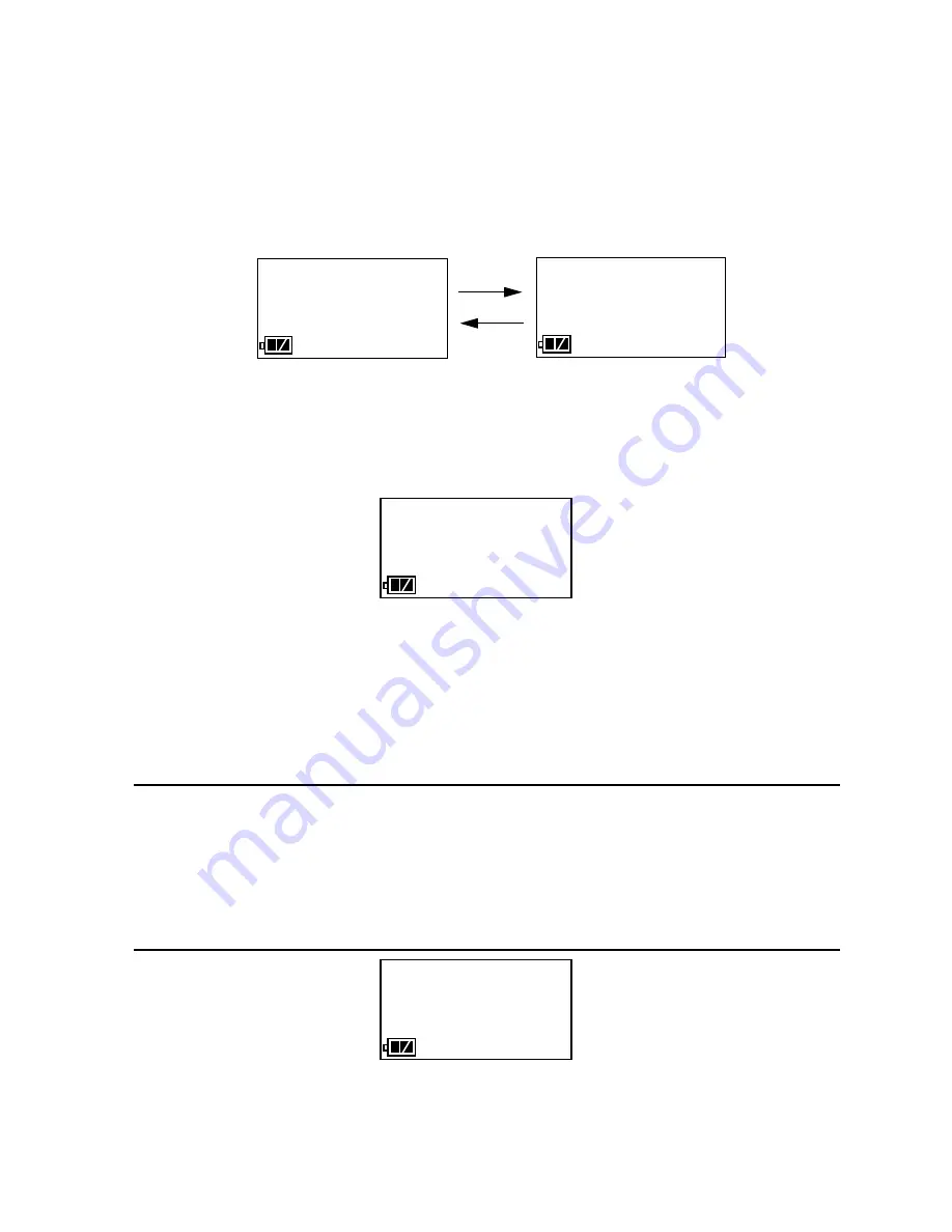
If one or more of the sensors fails the fresh air adjustment, the SDM-2009 
will abort the bump test and will not apply calibration gas. If this happens, 
the BUMP 

 LED will flash red indicating a failure and the following 

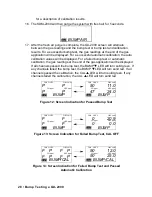
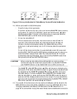
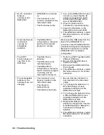
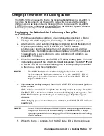
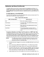
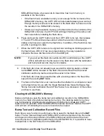
screens will alternate indicating the fresh air readings and which channels 
passed and failed the fresh air adjustment with a P (pass) or an F (fail). In 
the following examples, the CO channel failed.   

 Figure 11: Failed Fresh Air Adjustment

In this case, continue with step 18.

 14. The SDM-2009 will apply calibration gas to the instrument for the time defined 

by the GAS bump test parameter.    

 15. The SDM-2009 will analyze the results.

If the bump test passes, continue with step 16.

If the bump test fails, and CAL is set to OFF, continue with step 16.

If the bump test fails, and CAL is set to ON, a calibration will automatically 
begin and calibration gas will continue to flow. The CAL 

 LED will begin 

to flash amber. 

NOTE:

Calibration gas will continue to be applied so that the total gas 
application time is the time defined by the GAS calibration parameter. 
This time includes the time that the instrument was being bump tested. 
If the GAS 

calibration parameter

 is set to 90 seconds and the GAS 

bump test parameter

 is set to 30 seconds, the instrument will sample 

gas for an additional 60 seconds if the bump test fails to bring the total 
exposure time to 90 seconds. 

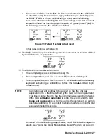
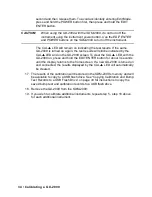
At the end of the calibration gas application, the SDM-2009 will analyze the 
results. See “Using the Single Module Data Viewer Program” on page 43 

          P            P               

ZERO    NG

CO ppm                      H2S ppm

CH4   %LEL                     OXY vol%

         F            P              

    0           12.0    

ZERO    NG

CO ppm                      H2S ppm

CH4   %LEL                     OXY vol%

   45            0.0     

47         11.0

  BUMP    G 1 

CO ppm                      H2S ppm

CH4   %LEL                     OXY vol%

49         23.0

47         11.0

  B/CAL   G 1

CO ppm                      H2S ppm

CH4   %LEL                     OXY vol%

49         23.0

Содержание SDM-2009

Страница 1: ...www rkiinstruments com SDM 2009 Docking Station Standalone Configuration Operator s Manual Part Number 71 0261RK Revision B Released 2 17 17 ...

Страница 2: ...sts local repair costs transportation costs or contingent expenses incurred without our prior approval THIS WARRANTY IS EXPRESSLY IN LIEU OF ANY AND ALL OTHER WARRANTIES AND REPRESENTATIONS EXPRESSED OR IMPLIED AND ALL OTHER OBLIGATIONS OR LIABILITIES ON THE PART OF RKI INSTRUMENTS INC INCLUDING BUT NOT LIMITED TO THE WARRANTY OF MERCHANTABILITY OR FITNESS FOR A PARTICULAR PURPOSE IN NO EVENT SHAL...

Страница 3: ...er 5 USB Cable 6 Air Filter and Sample Tubing 6 Instrument Cradle 8 Back Panel 9 Power Jack 9 Sample Fittings 9 PC Connection 9 Control Panel 10 Front Panel 12 Chapter 3 Preparing to Use the SDM 2009 13 Overview 13 Hardware Assembly 13 Setting the Operational Parameters in Edit Mode 14 Bump Test Calibration Parameters 14 Turning on the SDM 2009 with an Instrument 16 Setting the Bump Test Parameter...

Страница 4: ...9 Copying Calibration and Bump Test Records 39 Clearing the SDM 2009 s Memory 40 Bump Test and Calibration Record Files 40 Bump Testing or Calibrating and Saving Files to a Flash Drive Multiple Times in One Day 41 Chapter 5 Single Module Data Viewer Program 42 Overview 42 Launching the Single Module Data Viewer Program 42 Data Viewing Window 43 Using the Single Module Data Viewer Program 43 Import...

Страница 5: ...calibration and bump test data files from the USB flash drive or from the computer s hard drive if the files have been transferred to the hard drive from the flash drive If you are using the PC Controller Program while operating in the PC controlled configuration you may retrieve instrument data bump test and calibrate up to 10 instruments at once Instrument information and data for each instrumen...

Страница 6: ...inimize the risk of personal injury CAUTION The operator of this instrument is advised that if the equipment is used in a manner not specified in this manual the protection provided by the equipment may be impaired System Requirements To use the Single Module Data Viewer Software your personal computer must meet the following requirements Operating Systems Windows XP Windows Vista Windows 7 Window...

Страница 7: ... of Calibration Gas Cylinders One calibration gas cylinder per bump test or calibration Standard Accessories AC Adapter USB Flash Drive Single Module Data Viewer Program SDM GX Docking Station PC Controller Program Inlet Air Filter Instruction Manual 10 Foot Long Exhaust Tube One 3 Foot Long Tube for GAS Fitting 10 Foot Long 3 16 Inch Tube for GAS manifolding used for PC Controlled Configuration o...

Страница 8: ... CAUTION Describes potential damage to equipment WARNING Describes potential danger that can result in injury or death Cautions Safety Information Use only polyurethane sample tubing with the SDM 2009 Consult RKI Instruments Inc for other materials Do not subject the SDM 2009 to infrared or intense light This may cause communication errors Do not expose the SDM 2009 to water Do not subject the SDM...

Страница 9: ...s a wall plug style adapter with a 5 foot cable The end of the cable has a plug that connects to the power jack on the SDM 2009 s back panel The AC adapter is rated 100 240 VAC input 12 VDC 1 2 A output 4 Port AC Adapter The 4 port AC adapter is a wall plug style adapter with four 5 foot cables The end of each cable has a plug that connects to the power jack on the SDM 2009 s back panel The AC ada...

Страница 10: ...th of 3 16 inch ID polyurethane tubing is provided to connect the regulator on a calibration cylinder to the GAS fitting on the back panel One 10 foot length of 3 16 inch ID polyurethane tubing is provided for manifolding the GAS fitting This tubing is only needed in the PC Controlled configuration of the SDM 2009 In addition a 10 foot length of 5 16 inch ID polyurethane tubing is provided for con...

Страница 11: ...s included with the SDM 2009 but is not needed for the Standalone configuration It is used for the PC Controlled configuration Two T fittings are included with the SDM 2009 The larger fitting is for the exhaust tubing The smaller fitting is for the GAS tubing Neither T fitting is needed for the Standalone configuration They are used in the PC Controlled configuration Figure 5 Check Valve For Exhau...

Страница 12: ...bration gas to the sensors during a bump test or calibration An infrared IR port at the back of the cradle lines up with the GX 2009 s IR port when it is inserted in the cradle and is used to communicate with the GX 2009 A retaining tab that holds the GX 2009 in the cradle is located to the right of the IR port EDIT ENTER CAL POWER CHARGE SDM 2009 1SEC ON 3SEC OFF COPY GX 2009 OFF BUMP SDM 2009 Wi...

Страница 13: ...der Both fittings accept 3 16 inch ID tubing An exhaust fitting is located in the upper right corner It allows routing of the exhausted calibration gas to a convenient location This fitting accepts 5 16 inch ID tubing Even though the exhaust gas can be routed to an area to be safely dispersed the docking station should still be installed in a well ventilated area PC Connection A type B USB connect...

Страница 14: ...e an LED above them that indicates the status of the function controlled by that button The CHARGE LED is located above the POWER button and functions as a pilot LED a system failure LED and a charge indication LED Table 2 Control Button Functions Control Button Control Button Function s Control Button LED Function s BUMP Initiates a bump test Cancels a bump test Moves down a list of parameters De...

Страница 15: ...cancels an operation Turns off connected instrument when used with POWER button n a COPY Copies data to a USB flash drive Clears data from docking station memory when used with CAL button Indicates amount of docking station memory used Indicates status of copying function Indicates the result of a copy operation POWER Turns on the docking station Turns off the docking station Turns off connected i...

Страница 16: ...ion This port can be used to save calibration and bump test data to a USB flash drive This USB port is for use only in the Standalone configuration of the SDM 2009 NOTE The SDM 2009 does not support connection of a computer to the front USB port only a USB flash drive Figure 10 Front Panel ...

Страница 17: ...sert the round plug on the end of the AC adapter s cable into the power jack on the back of the SDM 2009 NOTE If you have multiple SDM 2009s and are using a 4 port AC adapter plug each of the round plugs on the end of the AC adapter into the power jack on the back of 4 separate SDM 2009s 4 Install the air filter so that the arrow on the filter that indicates direction of flow is pointing towards t...

Страница 18: ...ct for the bump test or calibration of any subsequent instruments until the parameter is changed again Bump Test Calibration Parameters There are four bump test parameters and two calibration parameters The two calibration parameters air sample time and calibration gas sample time are also bump test parameters The parameters are described below Table 3 below shows the factory settings for the bump...

Страница 19: ...the calibration gas concentration For example if the tolerance is set to 50 and the LEL calibration gas concentration is 50 LEL then the bump test gas reading for the LEL channel on the instrument must be 50 LEL 25 LEL The F10 F20 F30 etc options represent a fast bump tolerance If one of these F type tolerances is selected and the gas reading for the sensor s being tested is above the lower tolera...

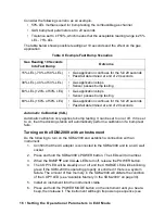
Страница 20: ...OWER button The LEDs will turn amber 3 When the BUMP and CAL LEDs turn off release the POWER button 4 The COPY LED will be steadily on or off and the CHARGE LED will be blinking green if the SDM 2009 is operating properly or solid red if there is a system failure The amount of free memory in the SDM 2009 will dictate the condition of the COPY LED see Available Memory in the SDM 2009 on page 39 5 I...

Страница 21: ...ument parameters When Cal Limit Display is set to On and Cal Limit Check is set to Can t Use if the GX 2009 is due for calibration the instrument will show a calibration expired failure screen and the buzzer and LED arrays will pulse for a few seconds The instrument will then connect to the SDM 2009 and display the home screen shown above in step 6 The CHARGE LED will begin to blink green When Cal...

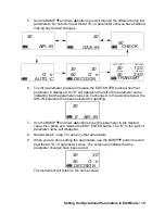
Страница 22: ...strument will alternate between the following screens that display the four bump test parameters and their settings The BUMP LED will turn green 4 If you wish to cancel setting the bump test parameters or were just viewing the parameters to confirm their values press and release the BUMP button to return to the home screen To continue and change parameters press and release the EDIT ENTER button T...

Страница 23: ... the AIR IN parameter has been selected for updating 7 Use the BUMP and CAL buttons to set the parameter to the desired value then press and release the EDIT ENTER button The E to the right of parameter name will disappear 8 Repeat step 6 step 7 to set any other parameters 9 When you are done setting the parameters use the BUMP button to scroll past the AUTO C parameter screen The screen will indi...

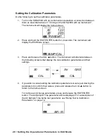
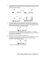
Страница 24: ...se the CAL button The instrument will alternate between the following screens that display the two calibration parameters and their settings 4 If you wish to cancel setting the calibration parameters or were just viewing the parameters to confirm their values press and release the CAL button to return to the home screen To continue and change parameters press and release the EDIT ENTER button The ...

Страница 25: ... the example below the AIR IN parameter has been selected for updating 7 Use the BUMP and CAL buttons to set the parameter to the desired value then press and release the EDIT ENTER button The E to the right of parameter name will disappear 8 Repeat step 6 step 7 to set any other parameters 9 When you are done setting the parameters use the BUMP button to scroll past the GAS IN parameter screen Th...

Страница 26: ...uments without an H2S channel Use Table 5 below as a guide in determining which calibration gas cylinder is appropriate for your system See Spare Parts List on page 52 for a list of available cylinder part numbers To connect calibration gas to the SDM 2009 do the following 1 If the area around the docking station is not considered a fresh air area an area free of combustible and toxic gases and of...

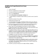
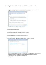
Страница 27: ... users on the computer or just for your user account then click Next to proceed to the Destination Folder window 12 The default installation folder C Program Files Single Module Data Viewer is displayed If you want to install the software in the default folder continue with step 8 If you want to install the software in a different location click Change and choose a new installation folder now and ...

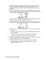
Страница 28: ...ent passed the bump test The bump test check tolerance is defined in Bump Test Check Tolerance CHE on page 15 If the automatic calibration parameter is set to ON then the SDM 2009 will automatically perform a calibration if the bump test fails Do the following to perform a bump test on a GX 2009 1 Confirm that the AC Adapter is connected to the SDM 2009 and to an AC wall socket 2 Press and hold th...

Страница 29: ...se if the GX 2009 is due for calibration the instrument will show a calibration expired failure screen and the buzzer and LED arrays will pulse for a few seconds The instrument will then connect to the SDM 2009 and display the home screen shown above in step 6 The CHARGE LED will begin to blink green When Cal Limit Display is set to On and Cal Limit Check is set to Confirm to use if the GX 2009 is...

Страница 30: ...est the gas flow to the instrument becomes too low the bump test will be aborted and the screen will indicate a flow failure If a flow failure occurs confirm all tubing connections are correct and that all lines are clear To return to the home screen press and hold the EDIT ENTER button for about 3 seconds To start another bump test press and release the BUMP button To perform a calibration press ...

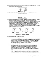
Страница 31: ...ep 16 If the bump test fails and CAL is set to ON a calibration will automatically begin and calibration gas will continue to flow The CAL LED will begin to flash amber NOTE Calibration gas will continue to be applied so that the total gas application time is the time defined by the GAS calibration parameter This time includes the time that the instrument was being bump tested If the GAS calibrati...

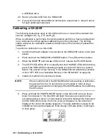
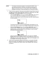
Страница 32: ...ayed If all channels passed the bump test the BUMP LED will turn solid green If any channels failed the bump test the BUMP LED will turn solid red If all channels passed the calibration the CAL LED will turn solid green If any channels failed the calibration the CAL LED will turn solid red Figure 12 Screen Indication for Passed Bump Test Figure 13 Screen Indication for Failed Bump Test CAL OFF Fig...

Страница 33: ...ss and hold the POWER button first then press and hold the EDIT ENTER button CAUTION When using the GX 2009 with the SDM 2009 do not turn off the instrument using the instrument power button Use the EDIT ENTER and POWER buttons on the SDM 2009 to turn off the instrument The BUMP or BUMP and CAL LEDs will remain on indicating the test results If the same GX 2009 is turned on again the test results ...

Страница 34: ...ll be off or on steadily and the CHARGE LED will be blinking green if the SDM 2009 is operating properly or solid red if there is a system failure The amount of free memory in the SDM 2009 will dictate the condition of the COPY LED see Available Memory in the SDM 2009 on page 39 5 Install a GX 2009 in the instrument cradle NOTE If the GX 2009 is left in the SDM 2009 after bump testing or calibrati...

Страница 35: ...for a few seconds The instrument will then connect to the SDM 2009 and display the home screen shown above in step 6 The CHARGE LED will begin to blink green When Cal Limit Display is set to On and Cal Limit Check is set to Confirm to use if the GX 2009 is due for calibration the unit will show the following screen and beep and flash the LED arrays for a few seconds indicating that calibration is ...

Страница 36: ...button 11 The SDM 2009 begins the calibration by applying fresh air to the instrument for the time defined by the Air calibration parameter 12 The SDM 2009 will perform a fresh air adjustment on the instrument If the air adjustment is successful the SDM 2009 will continue as described in step 13 below If one or more of the sensors fails the fresh air adjustment the SDM 2009 will abort the calibrat...

Страница 37: ...bration Figure 17 Calibration Results 16 After a successful or failed calibration To perform any other operations To perform a bump test press and hold the BUMP button until the pump starts To perform another calibration press and hold the CAL button until the pump starts To return to the home screen press and hold the EDIT ENTER button until the home screen appears To turn the GX 2009 off If the ...

Страница 38: ...nd on the GX 2009 screen To clear the CAL LED with the GX 2009 on press and hold the EDIT ENTER button for about 3 seconds until the display returns to the home screen If a new GX 2009 is turned on and connected the results displayed by the CAL LED will automatically be cleared 17 The results of the calibration will be stored in the SDM 2009 s memory and will be available to copy to a USB flash dr...

Страница 39: ...nections 4 If the fail condition continues replace the sensor s in the instrument 5 If the difficulties continue contact RKI Instruments Inc for further instruction Calibration fails The auto calibration values do not match the cylinder gas concentrations The calibration cylinder is out of gas or is outdated The calibration cylinder is not connected to the GAS fitting The instrument is not properl...

Страница 40: ...to the USB drive The USB drive is defective The USB drive is not inserted properly The SDM 2009 is connected to a computer the PC Controller program is running and an instrument is turned on 1 Perform a COPY operation with a different USB drive 2 Be sure that the USB drive is inserted correctly 3 Disconnect the SDM 2009 from the computer 4 If the difficulties continue contact RKI Instruments Inc f...

Страница 41: ...e pressed for 10 minutes 3 While the instrument is on the CHARGE LED will be blinking green When the instrument is turned off the CHARGE LED will blink amber The BUMP and or CAL LED will continue to be either green or red depending on the result of the previous bump test or calibration NOTE The SDM 2009 does not start charging the batteries until the instrument is off While the instrument is on th...

Страница 42: ...ll continue to blink amber while charging is taking place The SDM 2009 will take approximately 3 hours to charge a fully discharged GX 2009 If the charging process encounters a fail condition the CHARGE LED will turn steadily red 7 When the charge is complete the CHARGE status LED will turn solid green Batteries Too Drained for Standalone Operation If the NiMH batteries do not have enough power to...

Страница 43: ...ation and bump test records in the SDM 2009 s memory to a USB flash drive NOTE The USB port on the front of the docking station cannot be used to connect the SDM 2009 to a computer only to save calibration and bump test records to a USB flash drive 1 Confirm that the AC Adapter is connected to the SDM 2009 and to an AC wall socket 2 Press and hold the SDM 2009 s POWER button The LEDs will turn amb...

Страница 44: ...ay be incomplete 8 If the flash drive has not already been used with a docking station a folder named DAT will be created on the flash drive and a file with all the saved calibration and bump test records will be saved to this folder If the flash drive has been used before with a docking station the file will be saved to the existing DAT folder 9 The files on the flash drive can now be either tran...

Страница 45: ... its name will be the same as the new file In this case no information is lost since the second file saved to the flash drive includes all the records that were in the first file However if bump tests or calibrations are performed a copy operation is performed and the SDM 2009 s memory is cleared then additional bump tests or calibrations are performed and another copy operation is performed with ...

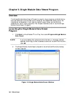
Страница 46: ...or use in other programs This chapter describes how to use the Single Module Data Viewer Program Launching the Single Module Data Viewer Program 1 Click Start on the Windows Icon Tray then select Programs Single Module Data Viewer NOTE If you are starting the software for the first time a message window appears informing you that a database has been created If this occurs click OK 2 The Single Mod...

Страница 47: ...t that initiate the various operations The upper left side of the window displays the contents of the database The lower left corner of the window has selection boxes that allow you to organize the data The upper right side of the window shows the contents of the item selected in the upper left side and the lower right side indicates the contents of the item selected in the area above it In the ex...

Страница 48: ...The files generated by the SDM 2009 are structured to be imported into the Single Module Data Viewer Program database To import data files into the database do the following 1 While in the Data Viewing Window click the Import button The Import Window will appear 2 Navigate to the location of the files that you want to import into the database 3 Select the files that you want to import or use the C...

Страница 49: ...he Serial No Station ID or User ID selection boxes in the lower left of the window are selected and the Base box appears next to these selection boxes with two radio buttons The data can be organized by either the data Type bump test and calibration data or by Date year and month The example below shows the data organized by Type Figure 21 Data in Base Viewing Format Type ...

Страница 50: ...se box disappears The example below shows the data organized by serial number Viewing the Data Once you have selected how you want to organize the data 1 Click the expanded view symbol next to an item folder or icon in the left side of the data viewing window or double click the item to view the contents below it Single click on an item to view the contents in the right side of the window If an it...

Страница 51: ...g data in base view format with the data organized by type expand the item bump test or calibration you wish to view Icons organized by year month will appear below the bump test or calibration icon Click on the item whose contents you wish to see The bump test or calibration files will be shown in the upper right side of the data view window Figure 23 Calibration Bump Test Files in Base View Form...

Страница 52: ...organized by year month appear in the left side of the window Expand the folder you want to see and click on the calibration or bump test folder The calibration or bump test files will appear in the upper right side of the window Figure 24 Calibration Bump Test Files in Base View Format by Date ...

Страница 53: ...t record a calibration or bump test where not all channels passed are highlighted in orange 5 To view the file contents click on the file in the upper right part of the data view window that you wish to view The contents in the file will appear in the lower right part of the window The contents include the instrument s serial number station ID user ID bump test or calibration time test gas and gas...

Страница 54: ...disk icon in it A Save As dialog box will appear for you to specify the filename file location and file type Select the Text files csv choice to save the information as a comma separated value file that may be opened with a spreadsheet program such as Microsoft Excel 10 To save files to the clipboard as they appear in the upper right part of the data view window click the Copy To Clipboard button ...

Страница 55: ...is ABCDE and is case sensitive You can change the password in the data view window To change the password perform the following 1 Right click in the upper right or upper left part of the data view window A window will appear that says Delete D Change Password C 2 Click on Change Password C A window will appear prompting you for the current password 3 Enter the current password and click the Curren...

Страница 56: ...the Exit button in the upper right corner of the data view window A confirmation window will appear 2 Click the OK button to exit the program or the Cancel button to return to the program Spare Parts List Table 8 Spare Parts List Part Number Description 06 1248RK Polyurethane tubing 5 16 inch OD x 3 16 inch ID for connecting to inlet fittings 06 1248RK 03 3 foot length of 5 16 inch OD x 3 16 inch ...

Страница 57: ...linder 34 liter steel 81 0076RK 03 Zero air cylinder 103 liter steel 81 0090RK 01 Three gas calibration cylinder 50 LEL CH4 12 O2 50 ppm CO 34 liter steel 81 0090RK 03 Three gas calibration cylinder 50 LEL CH4 12 O2 50 ppm CO 103 liter steel 81 0154RK 02 Four gas calibration cylinder 50 LEL CH4 12 O2 50 ppm CO 25 ppm H2S 58 liter aluminum 81 0154RK 04 Four gas calibration cylinder 50 LEL CH4 12 O2...

Отзывы: