74
Operating and Maintenance Instructions – 7 Hardware and software
Rittal Liquid Cooling Package Plus
7.2
Control unit for fan module
(RLCP fan)
7.2.1 Hardware
Fig. 66:
Control unit fan module – front
1
Power supply (X3)
2
Fuse (2.5 A)
3
Fuse (2.5 A)
4
Power supply for fan 1 (X4)
5
Power supply for fan 2 (X5)
Fig. 67:
Control unit fan module – rear
1
Socket for control cable (X26)
2
Socket for air outlet temperature sensor (X8)
3
Socket for air inlet temperature sensor (X9)
4
Socket for tachometer Fan 1 (X6)
5
Socket for tachometer Fan 2 (X7)
6
Status LED
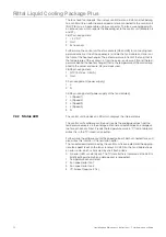
One control unit (RLCP fan) is assigned to two fan modules. It controls their in-
dividual components. The control voltage is +24V and is fed together with the
I
2
C bus through connector X26 of the control unit (Basic CMC).
X26 pin assignment:
1
Address signal (TTL Level)
2
Gnd
3
Address signal (TTL Level)
4
Address signal (TTL Level)
5
Gnd
6
+ 24 V DC
7
I
2
C (data)
8
I
2
C (clock)
The address signals can address up to six fan modules
X4 Fan 1 out
F6
Fuse max. 2,5 A T
F5
X3 AC in
(max. 230V/6A)
X5 Fan 2 out
1
2
3
4
5
X6
Speed 1
X9
Air 2
X8
Air 1
X26
I2C
X7
Speed 2
1
2
3
4
5
6


