59
Operating and Maintenance Instructions – 6 Installation – "Getting Started"
Rittal Liquid Cooling Package Plus
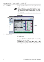
Graphical overview
The following values are displayed in the graphical overview in an illustrated
depiction of the Liquid Cooling Package Plus:
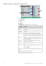
Tab. 7:
Measurements and display values in the graphical overview
Sensors
Four additional standard sensors can be connected to the control unit (Basic
CMC) to monitor additional physical parameters of the Liquid Cooling Package
Plus. The status of these sensors is displayed in this window.
Status line
The status line displays whether or not the unit is functioning problem-free or if
a warning or alarm message is present. The following displays are possible:
- No Alarm (green background)
- Warning (orange background)
- Alarm (red background)
Setting
values
Explanation
Server-in tem-
perature (3x)
Displays the actual temperature and the status of each tempera-
ture sensor on the cold air side of the LCP Plus.
The temperatures are displayed in real values in [°C]. The status of
the temperature sensors displayed in terms of colour:
- green = sensor o.k.
- red = sensor defective
Server-out
temperature
(3x)
Displays the actual temperature and the status of each tempera-
ture sensor on the warm air side of the LCP Plus.
The temperatures are displayed in real values in [°C]. The status of
the temperature sensors displayed in terms of colour:
- green = sensor o.k.
- red = sensor defective
Fanspeed (3x)
Displays the actual speed and the status of each fan.
The temperatures are displayed in real values in [rpm]. The status
of the temperature sensors displayed in terms of colour:
- green = sensor o.k.
- orange = speed is minor to 400 rpm
The arrangement and the numbering of the fan at the monitor is
equivalent to the real arrangement and numbering at the Liquid
Cooling Package Plus (fan 1, top/fan 6 bottom).
Flow rate
Displays the actual flow rate of the cooling medium in real values in
[l/min]. The status of the temperature sensors displayed in terms of
colour:
- green = sensor o.k.
- orange = sensor defective
Control valve
Displays the current setpoint for the position of the control valve in
[%]:
- 0% = valve closed,
- 100% = valve open.
Water tempe-
rature
Displays the actual temperature and the status of the temperature
sensor at the cooling water inlet and outlet.
The temperatures are displayed in real values in [°C]. The status of
the temperature sensors displayed in terms of colour:
- green = sensor o.k.
- red = sensor defective
Note:
Further explanations concerning the various setting options and features are
available in the CMC-TC system documentation.


